-- 6 2 --
cdte1de1
AC IGBT DTE 255, test and fitting instructions
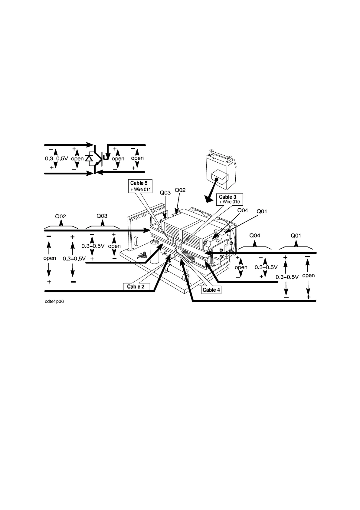
Disconnect cables 2, 3, 4, 5, wire 010 and 011 from the AC unit. Use a multimeter i n diode
test position to measure as shown in the diagram below.
Generally, if the IGBT module has burnt out, one or more of the high--speed fuses on AP09
and AP10 will also have blown. Check the fuses. The circuit diagrams for AP09 and AP10
are on page 53 and 54.
Warning: The IGBT modules are sensitive to ESD.
Test measuring AC IGBT modules, DTE 255
Fitting instructions for Q01 -- Q04
The IGBTs are extremely sensitive to ESD. Never touch an IGBT having an open gate input.
Apply appropriate ESD protection measures when fitting the IGBT’s.
Start by cleaning the heat sink, and then apply a thin, even layer of thermally conducting
grease to the contact surface of the IGBT. The purpose of this grease is to fill any hollows in
the surface of the IGBT and the heat sink: those parts of the IGBT and the heat sink that are
in true metallic contact may have such contact.
The order number for the thermally conducting grease is given under item 412 in the spare
parts list. Only the grease recommended by us may be used.
Fit the IGBT and tighten the screws to a torque of 1 Nm. Fur ther tighten the screws to a
torque of 3. 0 Nm, tightening them alternately.
Warning: An incorrectly fitted IGBT module can lead to failure. Do not tighten the screws
harder than 3.0 Nm.