-- 3 8 --
cdte1de1
R26 Adjustment for the minimum current reference.
R27 Adjustment for the maximum current reference (250A for the DTE
255 and 200A for the DTE 200).
R36 Is used in the DTE 200 to provide corr ect reading of the 200A range.
XA6 and 8 are bridged in the DTE 255.
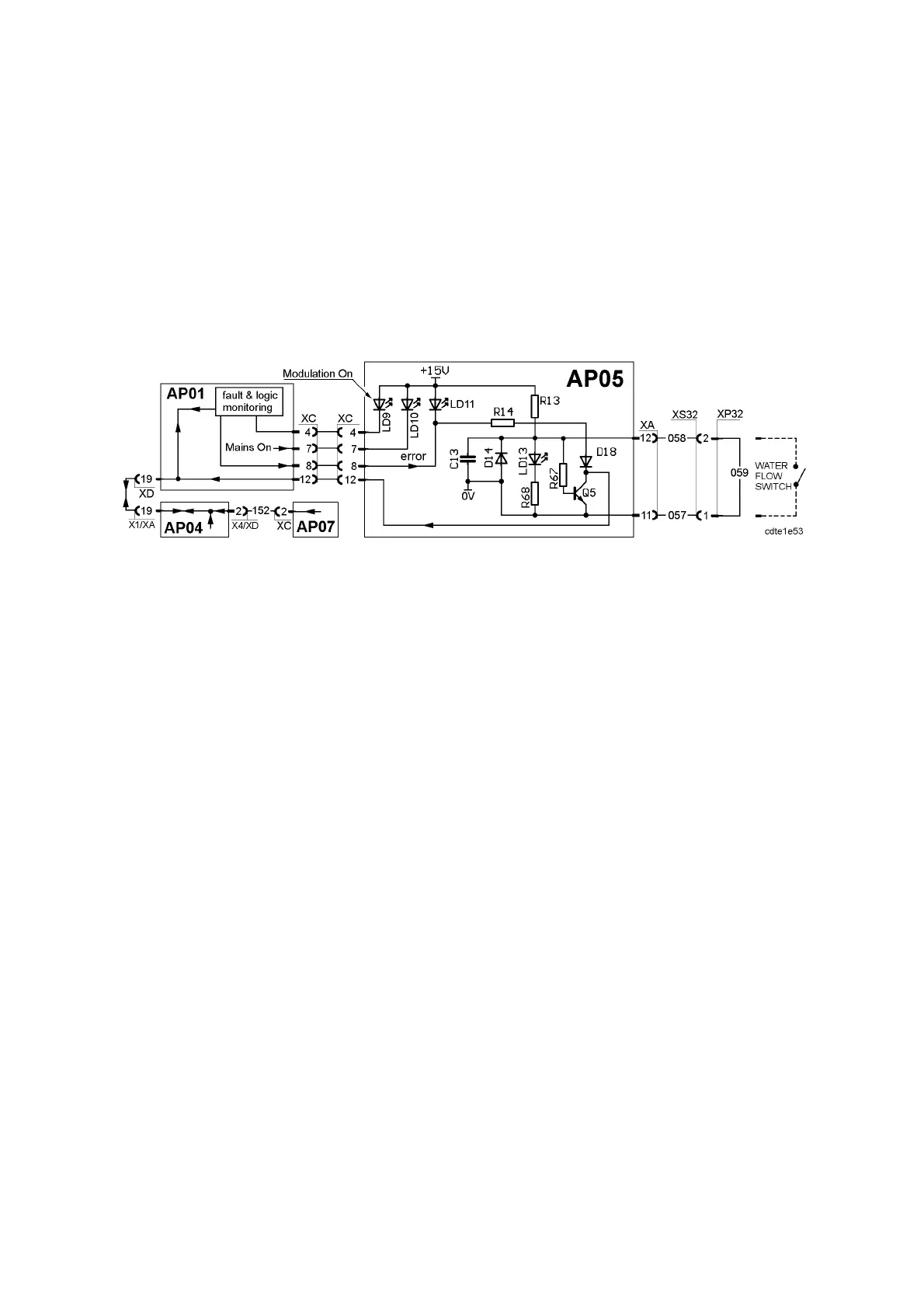
AP05:5 Error monitoring
Valid for all versions of circuit board AP05
Signal path for the error monitoring
All error m essages are monitored by processor board AP04, which stops the
machine if neccessary.
The voltage at connector XC:12 is about 0V when an error is present. During
normal operation, the voltage is 14--15V.
Diode LD9 is on when the PWM circuit on AP01 is generating pulses, e.g. when
the machine is producing an output voltage.
Diode LD10 is on when the mains switch is on: see AP01:1 on page 16.
Diode LD11 is on when the machine is stopped by an error:
S Overheating in the DC part of the machine. One or both of temperature
sensors ST01 and ST03 is/are activated. See description on page 17.
S Overheating in the AC part of the machine. Temperature sensor ST02 is
activated. See description on page 47.
S Overtemperature at AP07 discharge circuit: see description on page 48.
S Overvoltage at AP07 discharge circuit: see description on page 48.
S Lack of water flow: see LD13 below.
Diode LD13 is on when the connection between XA:11 and 12 is open. When
LD13 is on, LD11 is also on.
The LEDs LD9, LD10, LD11 and LD13 are visible on the front panel.