-- 1 8 --
cdte1de1
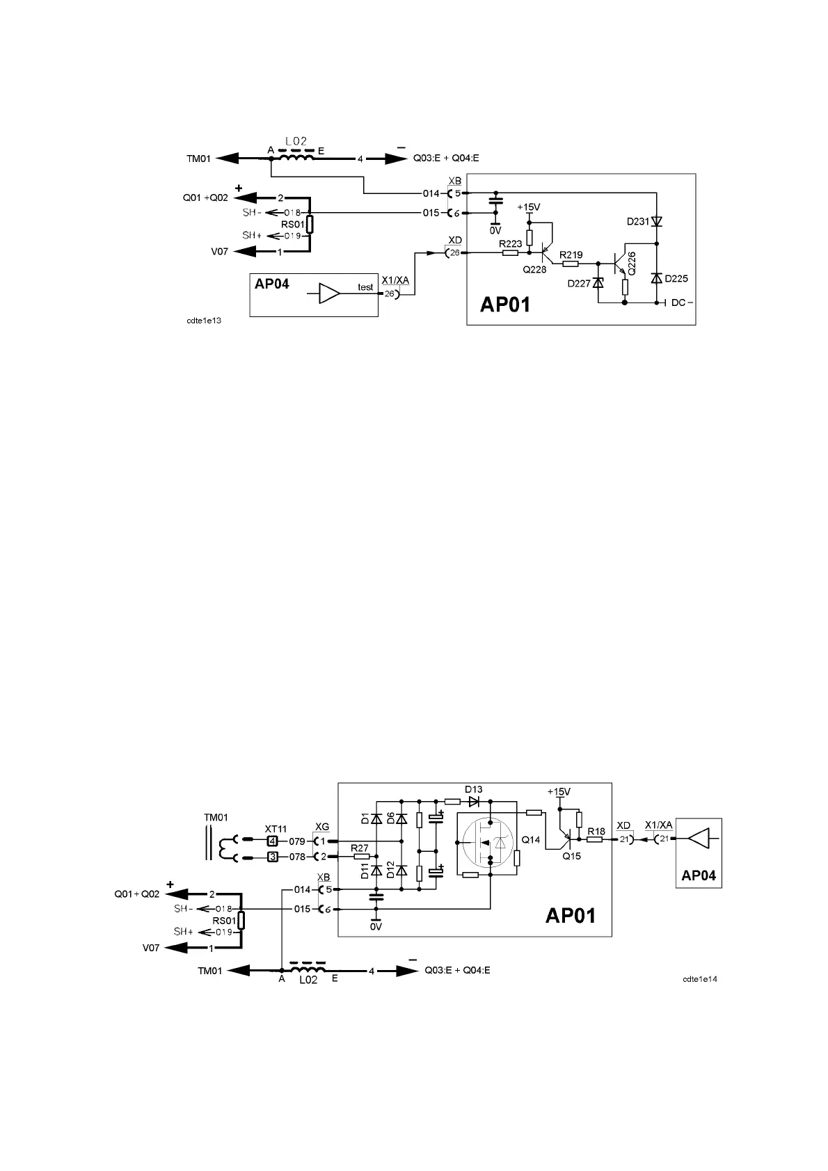
AP01:3a Lift Arc Test voltage
Lift Arc test voltage
In Lift Arc mode a test voltage is used to detect when the electrode is in contact
with the workpiece.
Normally the signal test from AP04 is +15V. When the torch trigger is
depressed it changes to 0V, activating transistors Q228 and Q226. DC--, which is
about --19V, is then connected in parallel with the welding voltage. The emitter
resistor of Q226 limits the current produced by DC-- to about 11mA.
The procedure for the Lift Arc start is as follows:
1. The torch switch is depressed, activating the test voltage and the gas valve.
2. The electrode contacts the workpiece. AP04 senses the change in voltage
via the arc voltage input (see the diagram on page 23). No action is
activated by the machine yet.
3. The electrode is lifted from the workpiece. AP04 senses the voltage change
and activates the modulation, i.e. the machine starts and strikes an arc.
This was a technical description of the Lift Arc start. The welder’s instructions
can be found on page 73.
AP01:3b HF Start vo ltage
Auxiliary HF start voltage
To achieve a good HF start, it is neccessary also to increase the voltage at the
electrode during the start. The voltage from an auxiliary winding on the main
transformer is used to produce the increased voltage, which is about 90--100V.