-- 1 7 --cdte1de1
Overwiev of the power supplies from circuit board AP01
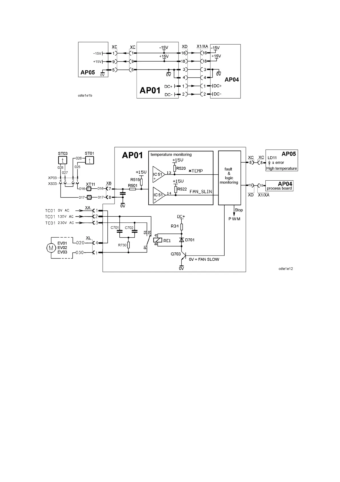
AP01:2 Temperature and fan monitoring
Overwiev of the temperature monitoring on circuit board AP01
Temperature sensor ST01 is fitted at one of the screws securing the IGBT
module Q05. Sensor ST03 is fitted on t he main transformer TM01. The sensors
are PTC resistors which are monitored by circuit board AP01.
When the temperature is below approximately 50_C the signal FAN_SLIN is 0V.
At higher temperatures the signal level changes to +5V and the fans (EV01,
EV02 and EV03) r un at full speed. When the temperature drops below 50_Cthe
signal level of
FAN_SLIN changes to 0V, but there is a 4--10 minute delay before
the fan speed changes to slow speed.
If the higher fan speed cannot remove the heat, so that the temperature continues
to rise, the signal
*TEMP changes at about 75--80_C from +10V to 0V. This
generates a stop signal to the PWM circuit and the processor board. This also
causes the error LED on the front of the machine to light. See the signal path for
error monitoring on page 38.
The machine cannot be restarted until it has cooled down.
When ST01 and ST03 are cold (20_C), the voltage between terminal XT11:1
and XT11:2 is about 0.3V. The resistance is about 60Ω for each of the sensors.
When the mains is switched on, the fans run at high speed for about five
seconds, and then switch to low speed.