-- 7 0 --
cdte1de2
OPERATION
General safety regulations for the handling of the equipment appear from page 68. Read
through before you start using the equipment!
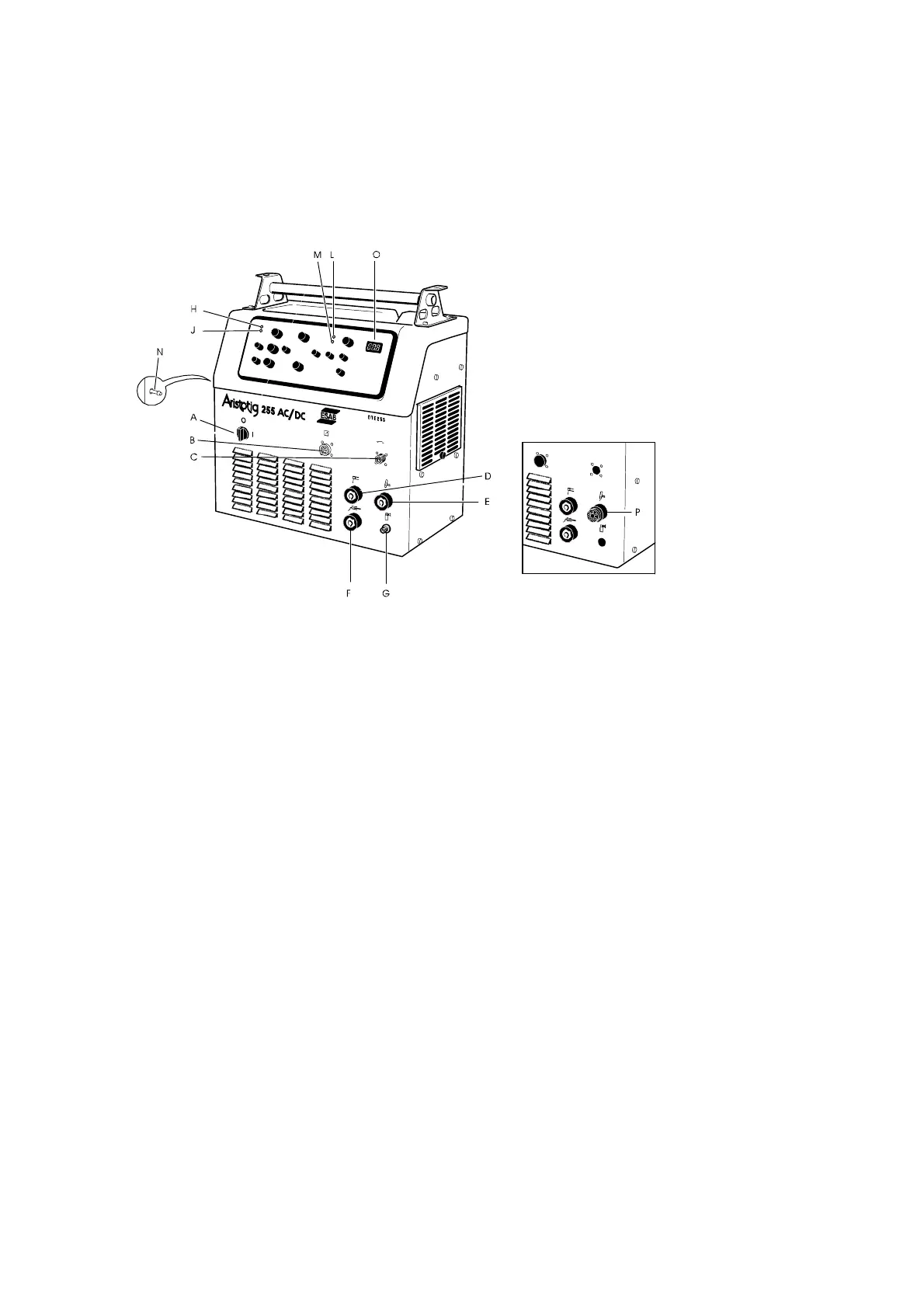
Controls and connections
Central connection
A Mains switch ON/OFF H Mains voltage ON, LED
B Connection for remote control unit J Welding voltage ON, LED
C Torch connector L Error / Overheating, LED
D Connection for electrode holder (MMA) M Flow guard, LED
(In operation when the cooling unit is
connected)
E OKC connection for TIG torch N Connection for shielding gas to the machine
F Return cable connection O Control unit, digital display
G Shielding gas connection P Central connection for TIG torch
N.B. The positions C and G are dropped when the central connection is used.
When the mains switch is switched on, the LED (H) goes on.
When open circuit voltage is applied LED (J) goes on.
When an error occurs, for example overheating, LED (L) goes on.
When there is no water flow LED (M) goes on.
When there is a fault that can cause temporary high output voltage, the LED (J) switches off,
(output voltage has been switched off). When idling for longer than 30 minutes, the output
voltage is switched off and LED (J) goes out.
Restart by turning the switch (1) to TIG mode and then back to MMA mode.
Remote control unit
For both the TIG and MMA methods the welding curr ent can be adjusted by way of a remote
control unit. The welding power source registers automatically when a remote control unit is
connected.