-- 5 8 --
cdte1de1
SER VICE INSTRUCTIONS
Soft starting
Note: NEVER use a mains fuse with higher rating than 16A.
We recommend that you perform the soft start when any components have been replaced. The
soft start procedure is also useful to use when fault tracing.
A special test circuit board (order no. 0486 640 880) is required for soft starting.
It is described on page 64.
1. DTE 255: Remove wires 090 and 007 from rectifier unit AP03. Diagram on page 12.
DTE 200: Remove wires 090 and 007 from rectifier V02. Before disconnecting, mark
the heat sink with a + where wire 007 is connected to V02. See the diagram on page 14.
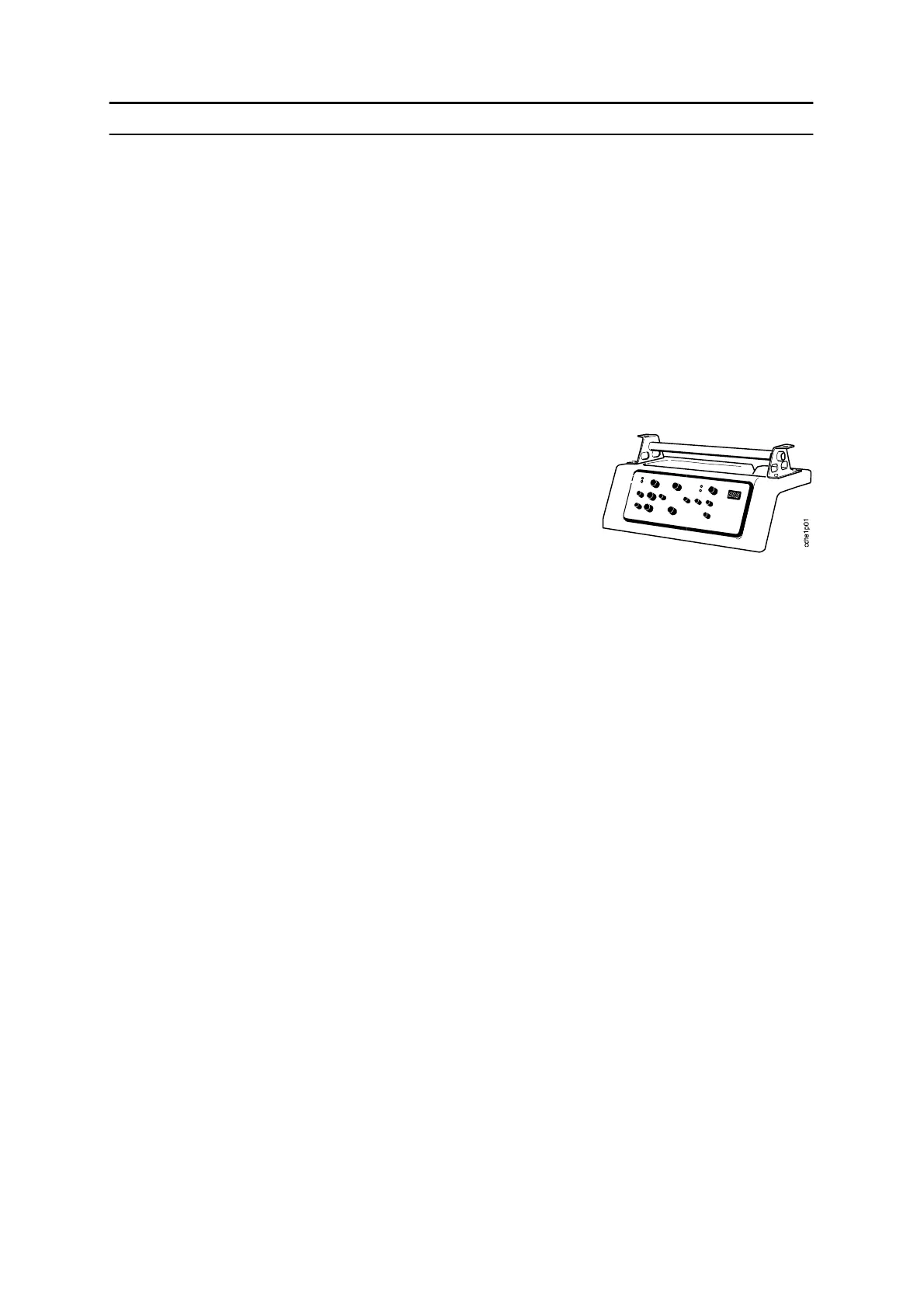
2. Remove the top cover with the front panel and circuit
board AP05. (Unscrew four screws at the handle and
two screws below the front panel).
Disconnect all cables from AP05.
NOTE: The cable lug on the yellow/green ground cable
has a lock function.
Top cover with panel and circuit board
3. Remove the screening box which is fitted over the circuit boards.
Remove connector XD (the ribbon cable to AP04) from cir cuit board AP01. See the
component positions on page NO TAG.
4. Remove connector X4 from circuit board AP04 and connect it to XC on the test circuit
board. See the component positions for AP04 on page 31.
5. Connect the two ribbon cables from the test circuit board to AP01.
Test XA to AP01 XD, test XB to AP01 XC.
6. Connect a regulated external 30V DC power supply to wire 090 and 007, with the
positive connected to 007.
The power supply m ust have a current limit set to a maximum of 1A.
7. Set the selector switch on the test board to position 1: OFF. Set the potentiometer on the
test board to about 20% from minimum position. (Min. pos. = max. anti clockwise)
Connect a multimeter to the welding outlets. Connect the positive terminal to XS13
(MMA) and the negative to XS14 (workpiece). Select DC voltage on the multimeter.
Leave the meter connected throughout the whole softstarting procedure.
8. Switch on the machine. LEDs MAINS, TEMP and DC FAIL will briefly light up, and
then all except MAINS will go out.
Switch on the external DC power supply.
9. Set the selector switch to position 2: TEST ON.
The meter must show 17 to 20V. This voltage comes from connections AP01:XB5 and 6.
It is a test voltage used to detect when the electrode is in contact with the workpiece
when Lift Arc is selected. See description on page 18.