-- 7 1 --cdte1de2
If the remote control is to include the whole current range, the current must be set to max. on
the welding power source. Max. value = The reference value set on the welding power
source. This is also the value shown by the display on the DTE 255 prior to serial no.
844--950--xxxx. For other DTE 255 machines and DTE 200 the value set by the remote
control is shown by the display.
Protection against overheating
Three thermal cut--outs prevent the power source being overloaded as a result of too high
temperature. If this should happen, the welding current is interrupted and the yellow diode
(L) goes on. (See page 70.)
When the temperature has gone down, the welding current circuit is reclosed and the diode
goes out.
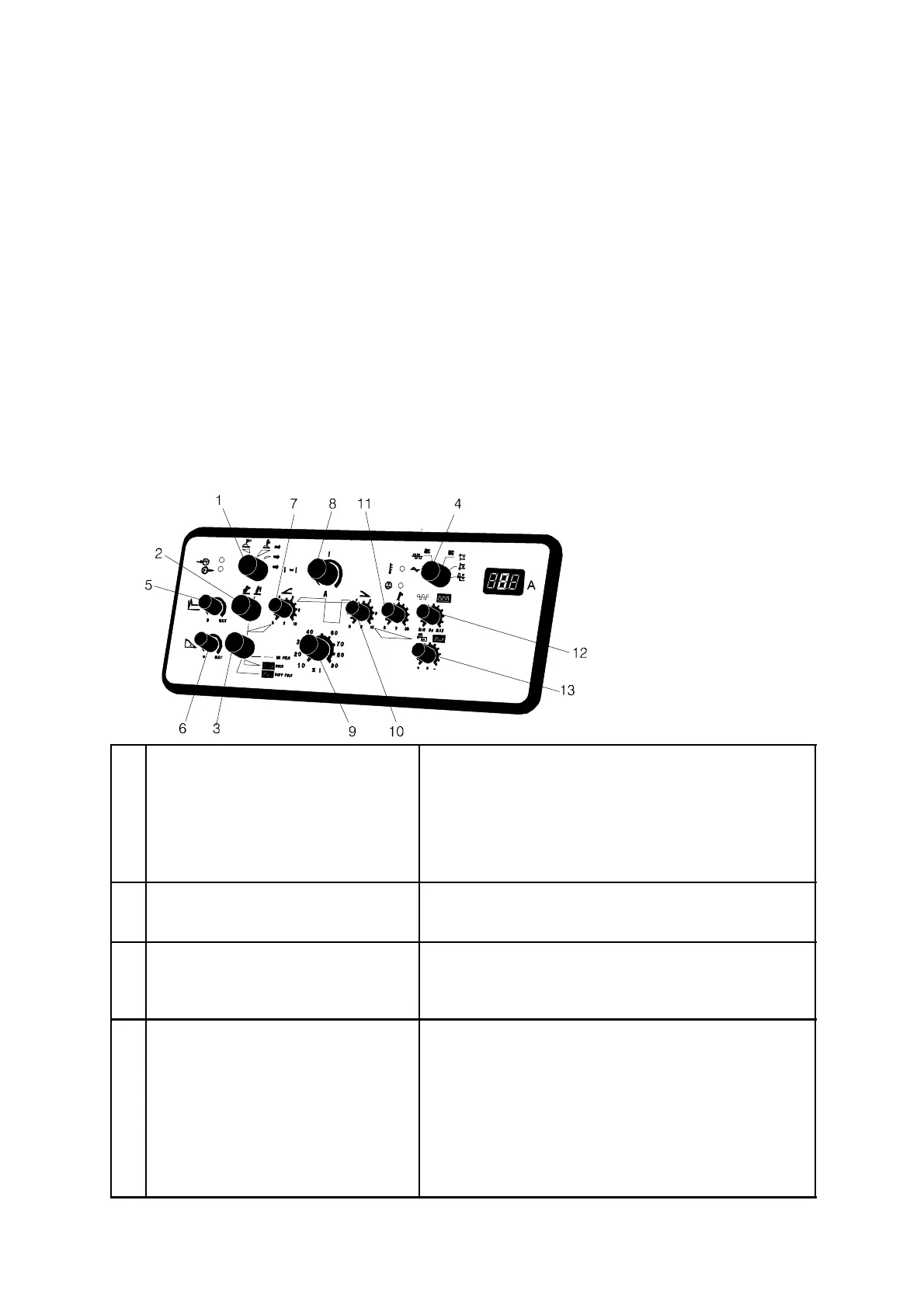
Control panel
1 Method selection switch
(SW3)
S MMA welding (hand welding electrodes)
S TIG, two--stroke (also for remote control)
S TIG, four--stroke
S TIG four--stroke with the possibility to shift between
two currents (shift function). See items 8 and 9
below for setting of the two currents.
2 Ignition selection switch
(SW2)
S HF ignition
S Lift--Arc ignition, see page 73.
3 Pulsing selection switch
(SW4)
S Non--pulsed welding, d.c. and a.c.
S Welding with square--wave pulsing; d.c. and a.c.
S Welding with trapezi--form pulsing; d.c. and a.c.
4 Polarity selection switch
(SW1)
S Alternating current
S Square--wave alternating current
S Direct current, negative electrode (normal in TIG
welding)
S Direct current, positive electrode
S Direct current, negative electrode, but with positive
electrode at the start (for example for 3.2 mm
electrodes, TIG welding).