-- 2 2 --
cdte1de1
AP01:7 Primary overcurrent protection
Primary current monitoring circuits
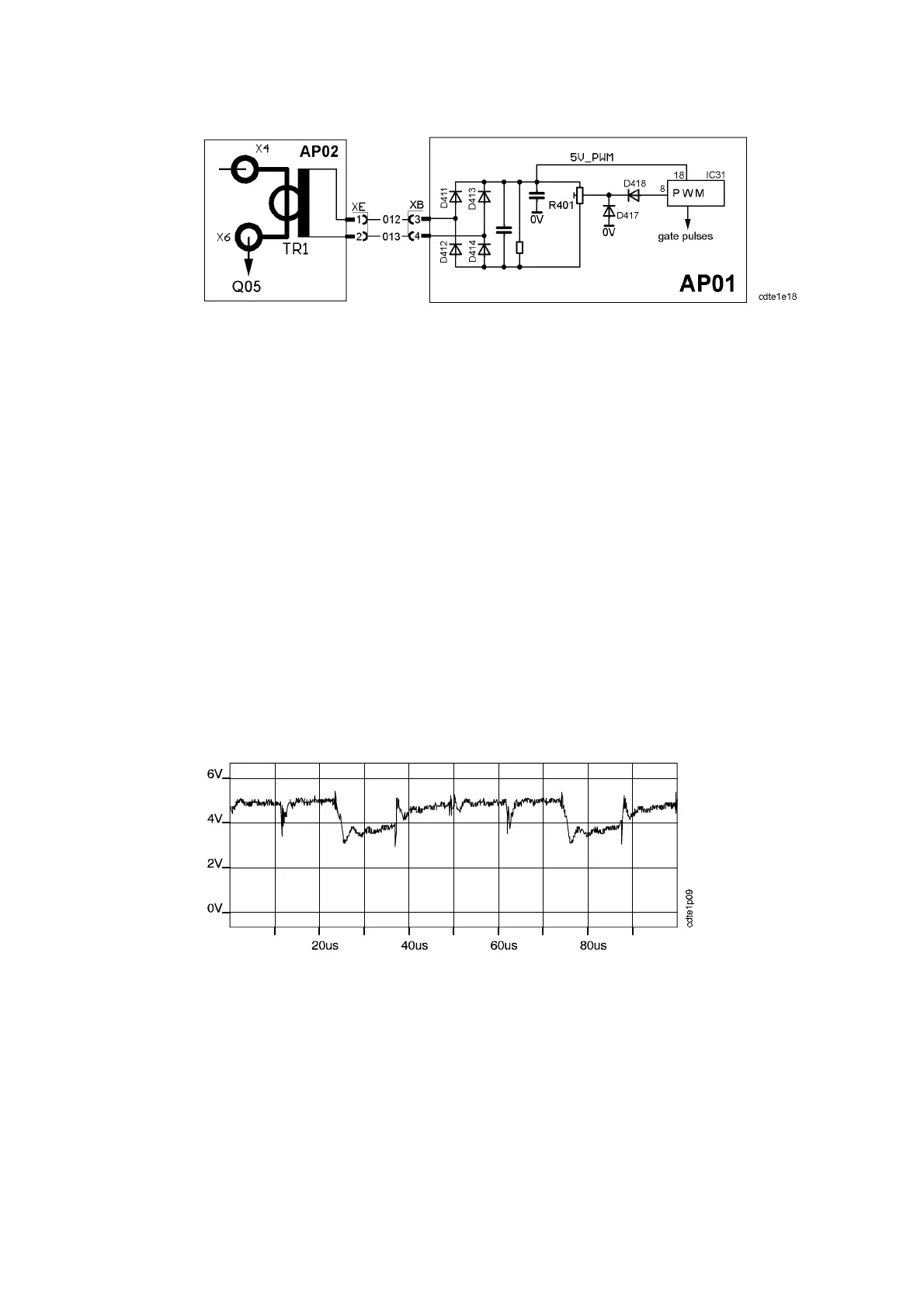
Current transformer TR1 is mounted on circuit board AP02, see the diagram on
page 27. The signal fr om TR1 is rectified on AP01. Potentiometer R401 (which
is factory--adjusted) adjusts the level of the signal to that needed to shut down
the PWM controller.
R401 has been adjusted to switch off the power source at a current
corresponding to 320A welding current under normal conditions. The shut down
input at IC31:8 is at +5V when the circuit is enabled for operation. If the input is
pulled down to 0V, the output signals are blocked.
When the PWM circuit is blocked there is no current, i.e. no overcurrent. The
PWM circuit is then automatically soft--started, which means that it slowly
increases the current. If the cause of the overcurrent, for example a short--
circuited secondary rectifier diode, is still present. The shut down input will be
pulled down again, and this action will continue.
In case of primary overcurrent: There are no indications on the front panel, but
the machine cannot be used for welding.
NOTE: TR1 must never be operated with an open--circuit secondary
(= output). This could destroy it by flashover between the windings.
Signal measured at the cathode of D417
The signal above is measured at a welding current of 200A and 18V under
normal conditions. The higher the primary current, the more the signal is pulled
towards 0V.