-- 4 2 --
cdte1de1
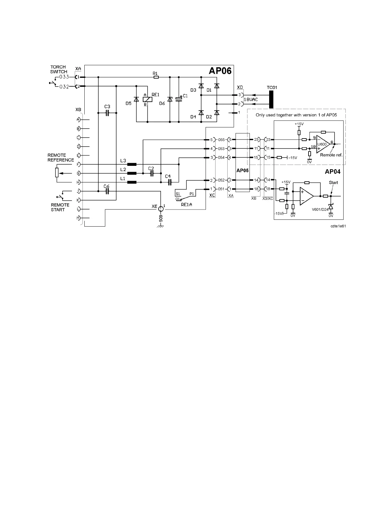
AP06 Start and remote control circuit board
Circuit diagram for circuit board AP06
START SIGNAL
Relay RE1 galvanically isolates the start switch from the machine. When the relay is
activated, the voltage at the cathode of V601/D24 is low (0 to --0.5V). When it is deactivated
the voltage is between 4 and 5V.
REMOTE REFERENCE
A potentiometer connected as in the diagram above can be used to set the remote reference. It
is also possible to use an external voltage to set the reference. When using an external
voltage, connect XB:G to 0V and XB:H to a voltage source.
For version 1 of AP05 the voltage source must be variable between 0 and +10V.
For version 2 of AP05 the voltage source must be variable between 0 and +5V.
When version 1 of circuit board AP05 is used the reference signal can be measured at
U600:8. When no remote control is connected the voltage is more than +5V. When the remote
control is in the min. position the voltage is 0V and when in the max. position it is +5V or
less.
With version 2 of circuit board AP05, the remote reference is connected as in the diagram on
page 35.
Note:
The internal current setting limits the current set by the remote control. See page 71 for
instructions.
DTE 255 before serial number 844--950--xxxx, with version 1 of circuit board AP05:
When using a remote control, the display will show the possible maximum current and not
the current set by the remote control.