-- 4 5 --cdte1de1
AP07:2 Gate pulses from AP07
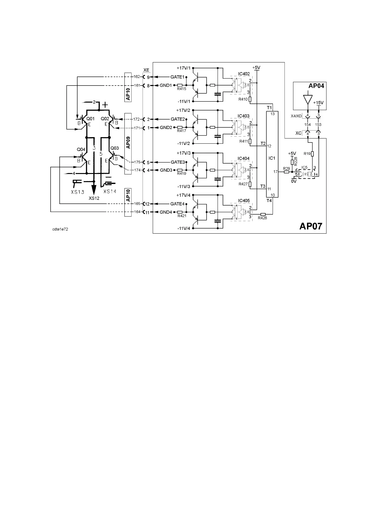
Gate control circuits for the AC IGBT’s in the DTE 255
The IGBTs are contolled by AP04. When connection XC:4 is low (=0V) the
polarity of the electrode is negative. NOTE: when measuring at XC:3, measure
relative to XC:1, which is 0V from AP04.
The IGBTs can have four different states:
1. All off (= open).
Error state. IC1, which also monitors the fault control on circuit board
AP07, has deactivated the IGBTs. IC1 outputs T1 -- T4 are high (+5V).
2. All on (= closed).
Is used during polarity change. The time for polarity change is controlled by
IC1, which holds its outputs T1 -- T4 at 0.5V for about 200ms.
3. DTE 255: Q01 and Q03 are on, Q02 and Q04 are off.
DTE 200: Q01:1 and Q02:2 are on, Q02:1 and Q01:2 are off.
The electrode is positive.
4. DTE 255: Q02 and Q04 are on, Q01 and Q03 are off.
DTE 200: Q02:1 and Q01:2 are on, Q01:1 and Q02:2 are off.
The electrode is negative.
When an IGBT is on, the voltage at the gate is +17V: when it is off the
voltage is --11V.
DTE 255 has two snubber boards, AP09 and AP10, which are described on
pages 53 and 54. DTE 200 has one snubber board, AP09, described on page 56.
The snubber boards carry fuses to protect the gate pulse driver circuits against a
short circuit in the IGBTs.
The test instructions for the IGBTs are given on pages 62 and 63. To check the
gate pulses see: SOFT STARTING, items 9 and 10 on pages 58--59.