-- 4 6 --
cdte1de1
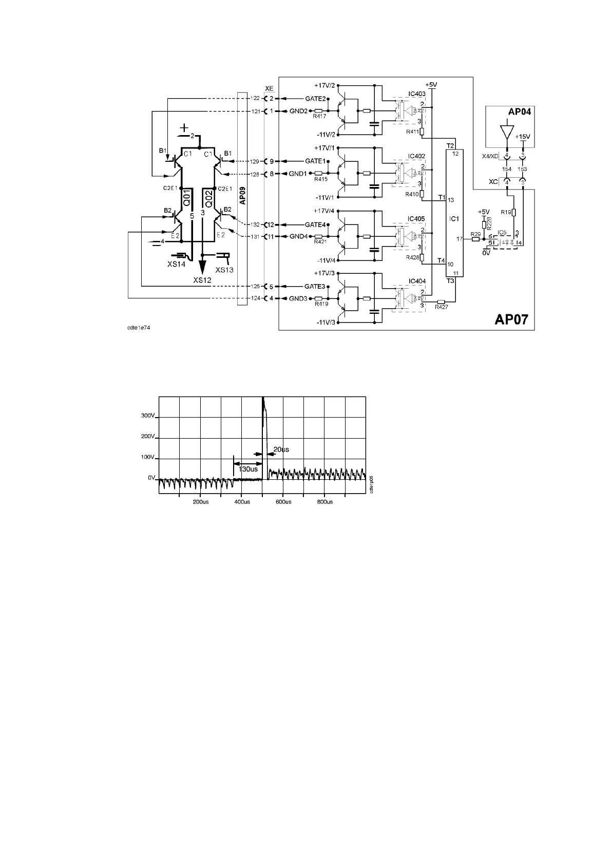
Gate control circuits for the AC IGBTs in the DTE 200
The picture below shows the voltage peak that makes the polarity change so fast
that no additional HF ignition is needed when the polarity is changed.
Voltage between the welding terminals XS14 and XS13 at 200A AC welding
Compare the actual waveform with the above waveform only during AC
welding with a standard torch. The wavef orm above is not valid for a resistive
load.
Looking at the picture above from left to t he right: First the welding voltage is
negative. Then all IGBTs are conducting for 130ms: the voltage is zero. Then
two IGBTs are turned on, producing a positve voltage peak of about 400V for
20ms, after which welding continues at normal welding voltage.
To ensure the correct voltage peak, the welding current must not be too high or
too low during the polarity change. This is controlled by the processor board
AP04.
If the current is lower than 50A, it will be increased to 50A shortly before all the
IGBTs are turned off. After the polarity is changed, the current is the same as it
was originally.
If the current is higher than 100A, it will be decreased to 100A shortly before all
the IGBTs are turned off. After the polarity is changed, the current is the same as
it was originally.
If the current is between 50 and 100A, there is no change in its value before the
polarity is changed.