-- 4 7 --cdte1de1
AP07:3 Temperature and voltage monitoring
This description applies to both the DTE 200 and the DTE 255. The IGBTs and
circuit board AP09 in the diagram below apply only to the DTE 255. The
corresponding diagr am for the DTE 200 is on page 56.
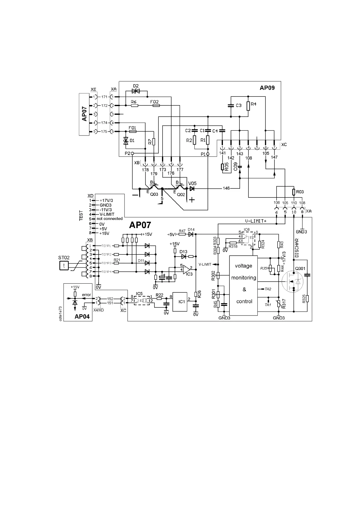
Schematic diagram for the temperature and voltage monitoring of the DTE 255
R35, TA1 and TA2 are only fitted to version 2 of the board.
FAULT MONITORING
If the temperature monitoring or the voltage control detect an error, IC1 will
send an error signal to the processor board. This stops the machine and shuts off
all IGBTs in the AC unit. See page 33 for the signal path of the error
monitoring.
TEMPERATURE MONITORING
The temperature monitor has a four--channel external input. Unused channels
must be short--circuited to disable them. The voltage divider at IC3:5 is set to
10.8V. If the input voltage at IC3:4 exceeds 10.8V, the output of IC3 is switched
to 0V. PTC resistor ST02, activates the output of IC3 when the temperature
exceeds about 75--80 _C. This results in an error signal to AP04.
ST02 is mounted on the cooling fins. When the temperature is below 30_C, the
resistance of ST02 is between 50 and 150Ω, (about 60Ω at 20_C).