-- 2 1 --cdte1de1
CHECKING THE GATE PULSES
a. Before attempting to measure the gate pulses to the IGBTs, it is essential to
disconnect the power supply from rectifier unit AP03.
DTE 255: Switch off the machine and remove wir es 090 and 007 from
rectifier unit AP03. See the wiring diagram on page 12.
DTE 200: Switch off the machine and remove wir es 090 and 007 from
rectifier V02. Mark the heat sink with a + where wire 007 is connected to
V02, before disconnecting. See the wiring diagram on page 14.
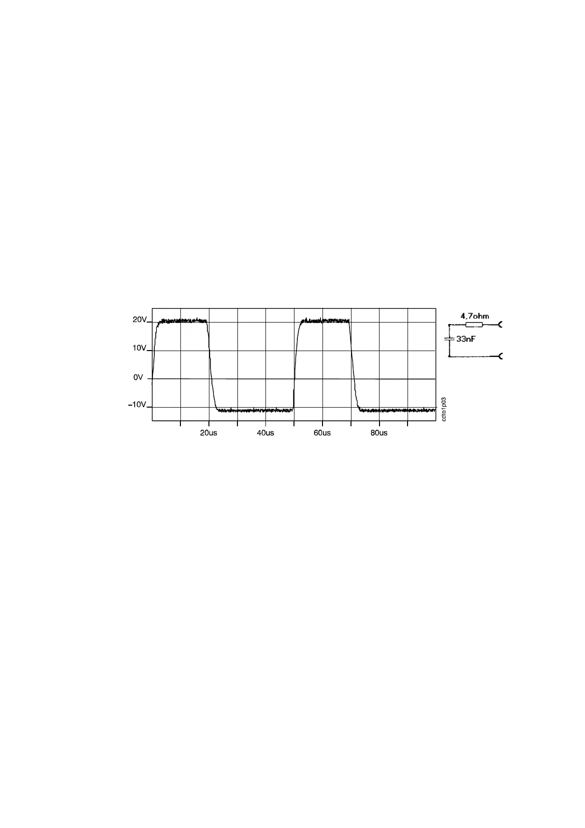
b. Disconnect AP11 and AP12 from AP01 and connect a gate load (4.7Ω
33nF) to each gate output (circuit board AP01 connector XI:1--2 and
XI:4--5).
See the diagram on page 20 and the component positions on page NO TAG.
c. Connect the oscilliscope with its screen to XI:4 and the probe to XI:5,
alternatively with the screen to XI:1 and the probe to XI:2.
Set the machine to MMA mode and switch it on.
The pulse shapes must be as shown below.
Gate load
Gate pulses measured with gate load at AP01
d. Measure the following pulse parameters on both gate outputs:
S Frequency: 20kHz ±0.5kHz.
S Pulse time: 19--21ms measured at the 0V level.
S The voltage of the positive pulse must be 18 to 20V
The voltage of the negative pulse must be --9 to --15V
e. If the pulses are within the tolerances, the pulse driver circuits are OK.
NOTE: When reconnecting wires 007 and 090, make sure that wire 007 is
connected to the positive of the rectifier.