OPERATION
6-4
6.2.2 FOR TIG PROCESS
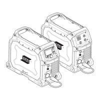
For TIG process (requires optional TIG accessories), connect the TIG torch power cable to the
negative [-] terminal (7), see illustration. Connect the gas inlet nut on the TIG torch to the gas
outlet connector (4) located on the front of the machine. Connect the gas inlet nut (12), on rear
panel, to a regulated shielding gas supply. Connect the work return lead to the return-cable
terminal (9). Connect the torch connector to the Torch connection (6) (see Figure 6-1).
6.3 POLARITY CHANGE
The unit’s power source is delivered with the polarity changeover cable connected to the
positive terminal. Some wires, e.g. self-shielded cored wires, are recommended to be welded
with negative polarity. Negative polarity means that the polarity changeover cable is connected
to the negative terminal and the return cable remains as the connection for the torch return-
cable. Check the recommended polarity for the welding wire you want to use. Refer to
electrode packaging for information relating to the correct electrode polarity. The polarity can
be changed by moving the polarity changeover cable to suit the applicable welding process
6.4 SHIELDING GAS
The choice of suitable shielding gas depends on the material. Typically, mild steel is welded with
mixed gas (Ar + CO2) or 100% carbon dioxide (CO2). Stainless Steel can be welded with mixed
gas (Ar + CO2) or Trimix (He + Ar + CO2). Aluminum and silicon bronze use pure argon gas (Ar).
In the sMIG mode (see section "sMIG mode" in the CONTROL PANEL chapter), the optimal
welding arc with the gas used will be automatically set.