OPERATION
6-27
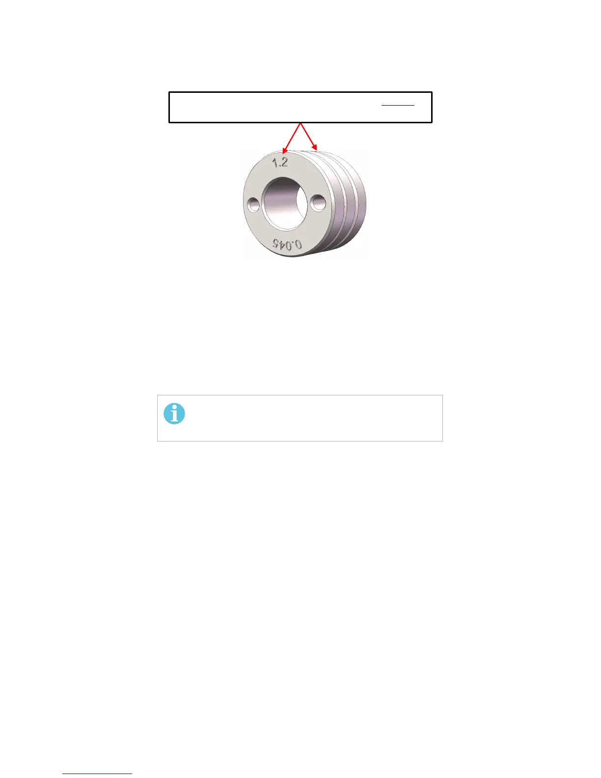
Figure 6-29. Wire-Feed Rollers Offered in Multiple Sizes
2. Tighten the Drive-Roller retaining screw by turning it in the clockwise direction.
Hand-tight is sufficient.
3. The wire must be installed through the wire-feed assembly (See Section 6.8.2
INSTALLING WIRE).
4. Close the pressure rollers on the wire.
5. Adjust the wire-feed pressure by adjusting the tension on the wire at the Wire-Feed
Rollers by turning the Tension Knob using the procedure SETTING WIRE-FEED
PRESSURE (see Section 6.10 ).
6. Close the cover on the wire-bobbin side of the EMP unit.
LABEL ON ROLLER-SIDE MATCHES WITH THE GOOVE ON THE OPPOSITE-
SIDE OF THE ROLLER.
If the wire was removed the wire will have to be re-
installed. Refer to Section 6.8.2 “INSTALLLING WIRE”.