OPERATION
6-33
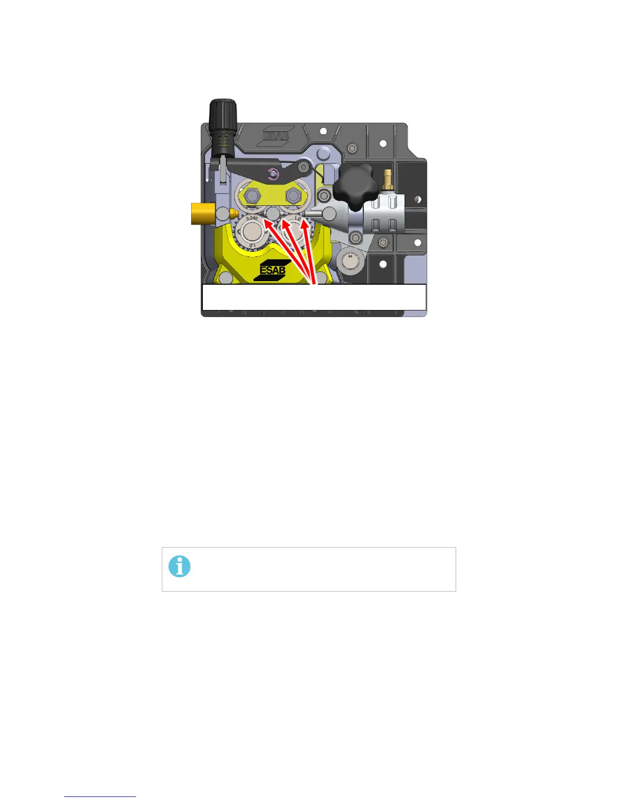
Figure 6-33. Verify Clearance of Both Guide Tubes
3. Access the bitter-end of the wire on the bobbin and cut off the length from the
bitter end to have a clean, straight, bitter-end. This is needed to allow a low-
resistance-travel re-install of the wire along the length of the torch cable to the
torch tip.
4. Feed the wire from the bottom of the bobbin through the Wire-Feed Guides laying
the wire in the grooves of the Wire-Feed Rollers as shown in Figure 6-30 . Lay the
wire into the INSIDE groove of the Wire-Feed Rollers. Continue feeding the wire until
it projects beyond the Euro-Adapter output side by a few centimeters.
5. Close the pressure rollers on the wire.
6. Re-connect the torch assembly on the EMP unit.
7. Power ON the EMP unit.
8. With the torch cable reasonably straight, feed the wire through the torch cable till
visible at its welding tip by depressing the trigger switch on the torch. Refer to the
relevant Torch manual for length of wire-protrusion at tip end.
ADJUST FOR, AND VERIFY, APPROXIMATELY 1 MM
CLEARANCE BETWEEN ROLLER AND GUIDE TUBES
The gas does not need to be connected for this