XRF6 RF Router Manual
Page 1-2 Revision 1.0 OVERVIEW
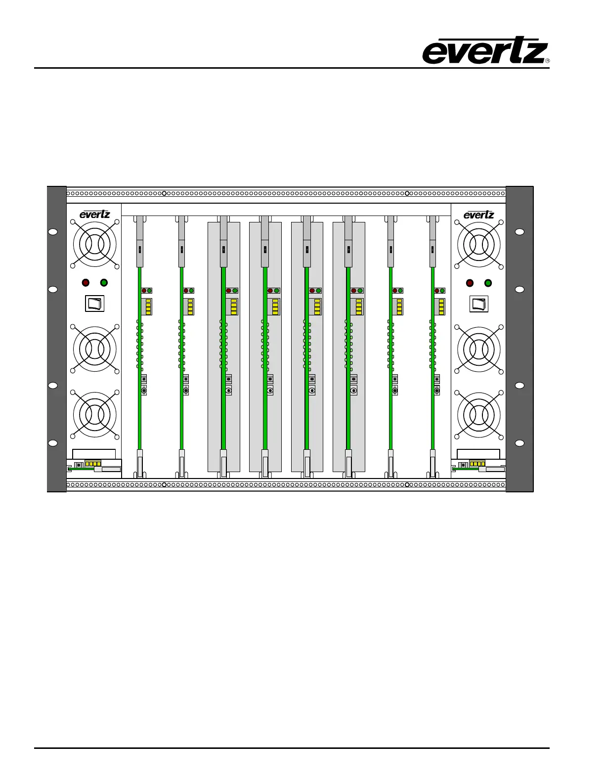
Input and output cards are housed in the 8 card slots located within the main (center) section of the frame.
The two leftmost card slots (1 and 2), and the two rightmost cardslots (7 and 8) may contain only input
cards, while the center 4 slots (3 through 6) may contain only output cards.
All signal and control connections are located on the rear panel of the frame, with the exception of the
firmware upgrade and configuration port, located near the front edge of all system cards.
X6RF-PS
FRAME
STATUS
PSU
STATUS
ON OFF
POWER SUPPLY
XRF6-FC
XRF6-I16LB
XRF6-
O16LB64x64
XRF6-I16LB
XRF6-I16LB
XRF6-I16LB
XRF6-
O16LB64x64
XRF6-
O16LB64x64
XRF6-
O16LB64x64
XRF6-FC
X6RF-PS
FRAME
STATUS
PSU
STATUS
ON OFF
POWER SUPPLY
Power
Supply A
Power
Supply B
Frame
Controller B
Frame
Controller A
SLOT 1SLOT 2SLOT 3SLOT 4SLOT 5SLOT 6SLOT 7SLOT 8
INPUTS
1-16
INPUTS
17-32
INPUTS
33-48
INPUTS
49-64
OUTPUTS
17-32
OUTPUTS
1-16
OUTPUTS
33-48
OUTPUTS
49-64
Figure 1-1: XRF6 router fully populated to 64x64 matrix size