XRF6 RF Router Manual
Page 3-2 Revision 1.0 CONFIGURATION
XRF6FC End PC End
2 row X
3 pin Berg
Pin 3 ft. Cable
(9501)
9 pin D
Female
Pin
Key 1 1
Rx 2 -------1a------ Tx 2
Tx 3 -------1b------ Rx 3
Tx Gnd 4 ----drain----- Gnd 5
Key 5
--- 6
Table 3-1: 7700PB Upgrade Cable (WA-S76)
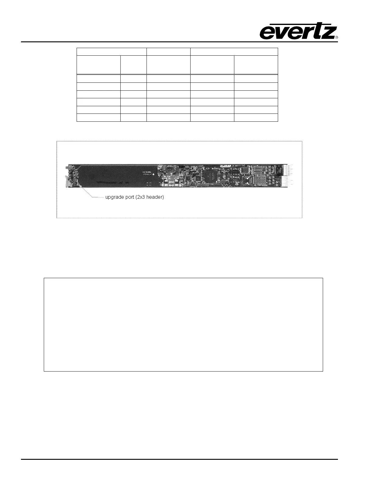
Figure 3-1: Location of the Frame Controller Upgrade/Configuration Port
After the frame controller is re-inserted into the frame, with power applied to the frame, the frame controller
will automatically initiate a boot up procedure, resulting in the top-level configuration menu being displayed
in the terminal program.
------------------------------------------------
| Main Menu |
| (X6RF-FC v1.00 b166) |
------------------------------------------------
(1) Network Configuration
(2) Router Configuration
(3) SNMP Setup
(4) Serial Control Port Configuration
(5) Show Card Status
(6) Engineering/Debug
(X) Exit
>
At the prompt, enter the number from the menu list, and press “ENTER”. Remember to save the changes
prior to exiting each configuration menu. Some of the settings require the frame controller to be re-booted
prior to the changes taking effect. This is accomplished by cycling power to the router frame, or by
executing the “Reboot” command from the Engineering/Debug menu.
The (x) option exits the current menu and moves up one menu level.