XRF6 RF Router Manual
STATUS LEDS Revision 1.0 Page 5-3
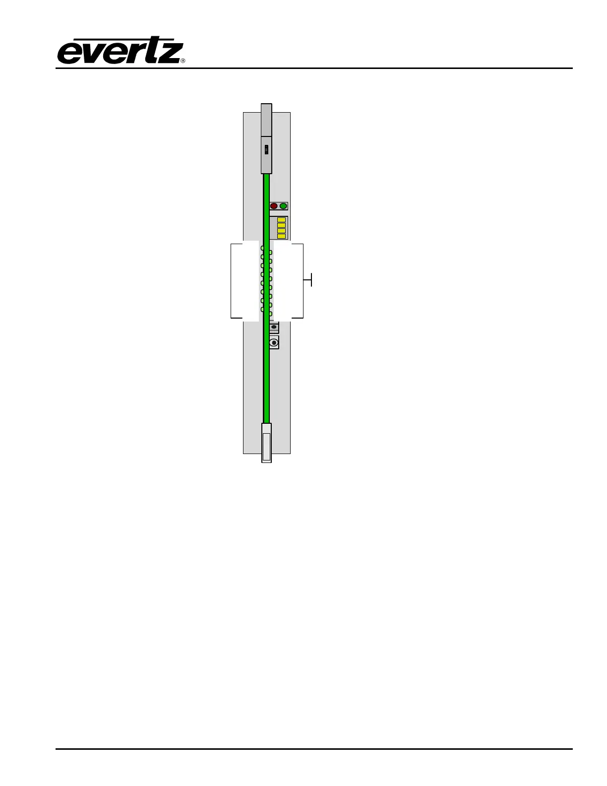
5.1.4. Output Card LEDs
XRF6-
O16LB64x64
4-Character
LED Display
Green: Board Active
Red: Fault
Green: Output active
Off: Output inactive
Output 1
Output 3
Output 5
Output 7
Output 9
Output 11
Output 13
Output 15
Output 2
Output 4
Output 6
Output 8
Output 10
Output 12
Output 14
Output 16
Figure 5-3: Output Card LED Indicators
The red and green LED pair located near the top of the board indicate overall board health status. The
green LED indicates that the input card has established communication with the frame controller. The red
LED indicates a card fault.
The output card has a group of 16 edge-mounted LEDs that correspond to an active RF output on the
card. An output is active when any RF input is connected to that output via the system crosspoint matrix.
An output is inactive (no LED illuminated) when no RF input is connected to it through the crosspoint
matrix.
The other LEDs on the output card are for engineering test indication, and are not yet assigned to user
functions. There are two LEDs next to the 4-character display, 1 red and 1 green, that alternate during
normal operation.