XRF6 RF Router Manual
Page 2-6 Revision 1.0 INSTALLATION
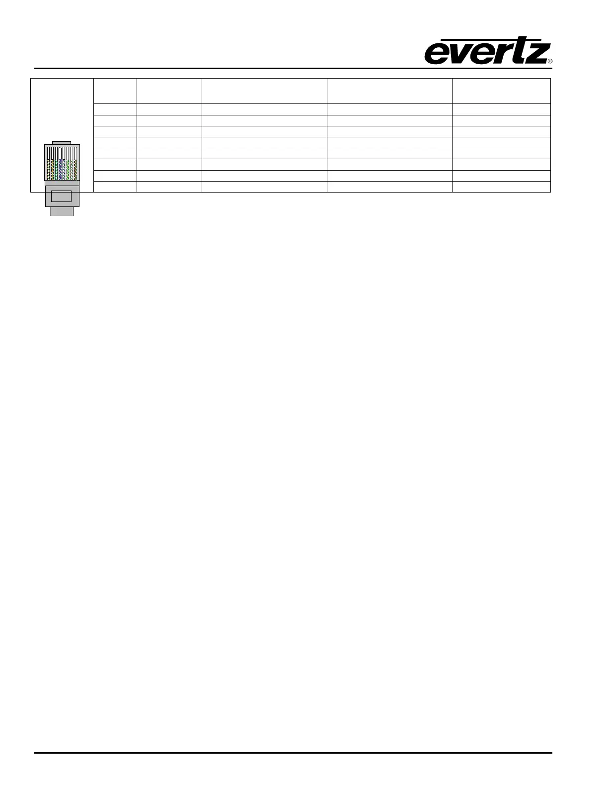
Pin # Signal EIA/TIA 568A AT&T 258A or
EIA/TIA 568B
10BaseT
or 100BaseT
1 Transmit + White/Green White/Oran
eX
2 Transmit
Green/White or White Oran
e/White or Oran
e X
3 Receive + White/Oran
e White/Green X
4 N/
Blue/White or Blue Blue/White or Blue Not used
re
uired
5 N/
White/Blue White/Blue Not used
re
uired
6 Receive
Oran
e/White or Oran
e Green/White or Green X
7 N/
White/Brown White/Brown Not used
re
uired
Pin
1
8 N/A Brown/White or Brown Brown/White or Brown Not used (required)
Table 2-3. Standard RJ45 Wiring Colour Codes
Note the following cabling information for this wiring guide:
• Only two pairs of wires are used in the 8-pin RJ 45 connector to carry Ethernet signals.
• Even though pins 4, 5, 7 and 8 are not used, it is mandatory that they be present in the cable.
• 10BaseT and 100BaseT use the same pins, a crossover cable made for one will also work with the
other.
• Pairs may be solid colours and not have a stripe.
• Category 5 cables must use Category 5 rated connectors.
The maximum cable run between the router frame and the supporting hub is 300 ft (90 m). The maximum
combined cable run between any two end points (i.e. router and X-NCP2 control panel or PC/laptop via
network hub) is 675 feet (205 m).
Devices on the Ethernet network continually monitor the receive data path for activity as a means of
checking that the link is working correctly. When the network is idle, the devices also send a link test
signal to one another to verify link integrity. Each RJ-45 connector is fitted with two LEDs to monitor the
Ethernet connection.
10/100
This Amber LED is ON when a 100Base-TX link is last detected. The LED is OFF
when a 10Base-T link is last detected (the LINK LED is ON). Upon power-up the
LED is OFF as the last detected rate is not known and therefore defaults to the
10Base-T state until rate detection is completed.
LN/ACT This dual purpose Green LED indicates that the Base Station has established a
valid linkage to its hub, and whether the Base Station is sending or receiving data.
This LED will be ON when the Base Station has established a good link to its
supporting hub. This gives you a good indication that the segment is wired
correctly. The LED will BLINK when the Base Station is sending or receiving data.
The LED will be OFF if there is no valid connection.
2.6. Inserting and Removing I/O and Frame Controller Cards
The XRF6 is a modular system, employing plug-in circuit cards for input, output and frame controller
modules. Each of these cards are easy to remove and insert, facilitating simple system expansion or
service.
2.6.1. Inserting Input or Output Cards
1. Orient the card vertically, such that the black plastic lever is on the bottom, while the metal card
ejector/latch is on the top.