XRF6 RF Router Manual
OVERVIEW Revision 1.0 Page 1-3
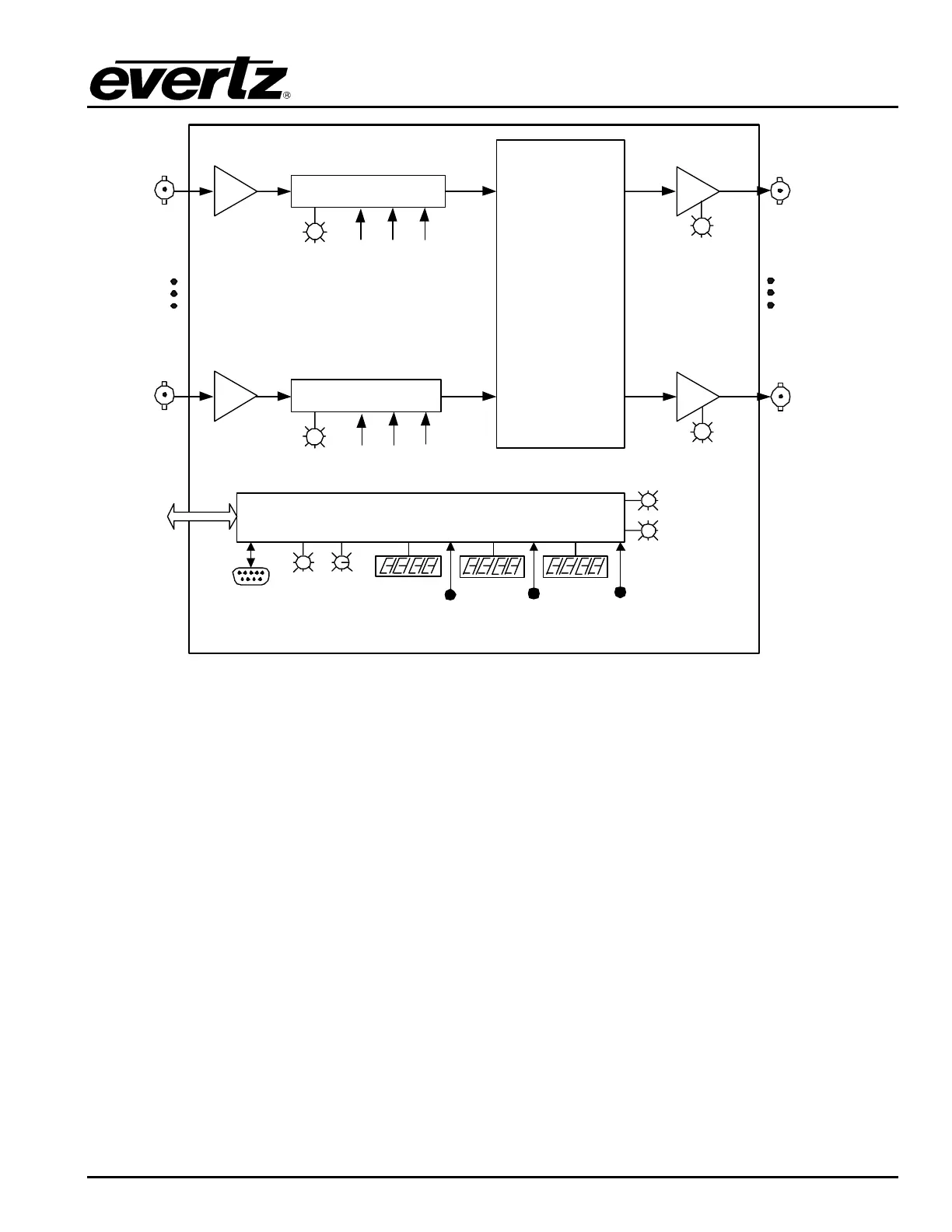
Vist aLINK®
Int erf ace
Board
Act iv e
LED
CONTROL / INDICATION
Serial Control
RS 232/RS 422
Frame
Status
LED
Power
Supply
Status
LED
Output Card
LED Display
Fault
LED
Output
Card-Edge
Control
N x M
Crosspoint
Matrix
M
1
N
M = 16, 32, 48, 64
RF
INP UTS
RF
OUTPUTS
N = 16, 32, 48, 64
AGC/Manual Gain
Input
Status
LED
AGC/Manual Gain
Input
Status
LED
SquelchOutput
Level
Gain
Control
Squelch
Output
Level
Gain
Control
1
Output
Act iv e
LED
Output
Act iv e
LED
Input
Card-Edge
Control
Input Card
LED Display
Frame
Controller
Card-Edge
Control
Frame
Controller
LED Display
Figure 1-2: XRF6 Block Diagram
1.1. HOW TO USE THIS MANUAL
This manual is organized into 8 sections: Overview, Installation, Configuration (chapters 3&4), Operation,
Technical Description, and XRF6 firmware upgrades.
Chapter 1 contains a quick summary of the router features and a glossary to define concepts and terms
used throughout the remainder of the manual.
Chapter 2 gives a detailed description of the rear panel connectors and a guide for connecting the router
to your existing system.
Chapter 3 describes the configuration of the router using the frame controller configuration port.
Chapter 4 describes the configuration of the router using the input card edge interface.
Chapter 5 gives a description of router operation using the optional remote control panel.
Chapter 6 provides a description of the router control panel and VistaLINK
®
monitoring application.
Chapter 7 lists the specifications for the XRF6 router.
Chapter 8 provides information on upgrading the XRF6 firmware.