XRF6 RF Router Manual
INSTALLATION Revision 1.0 Page 2-5
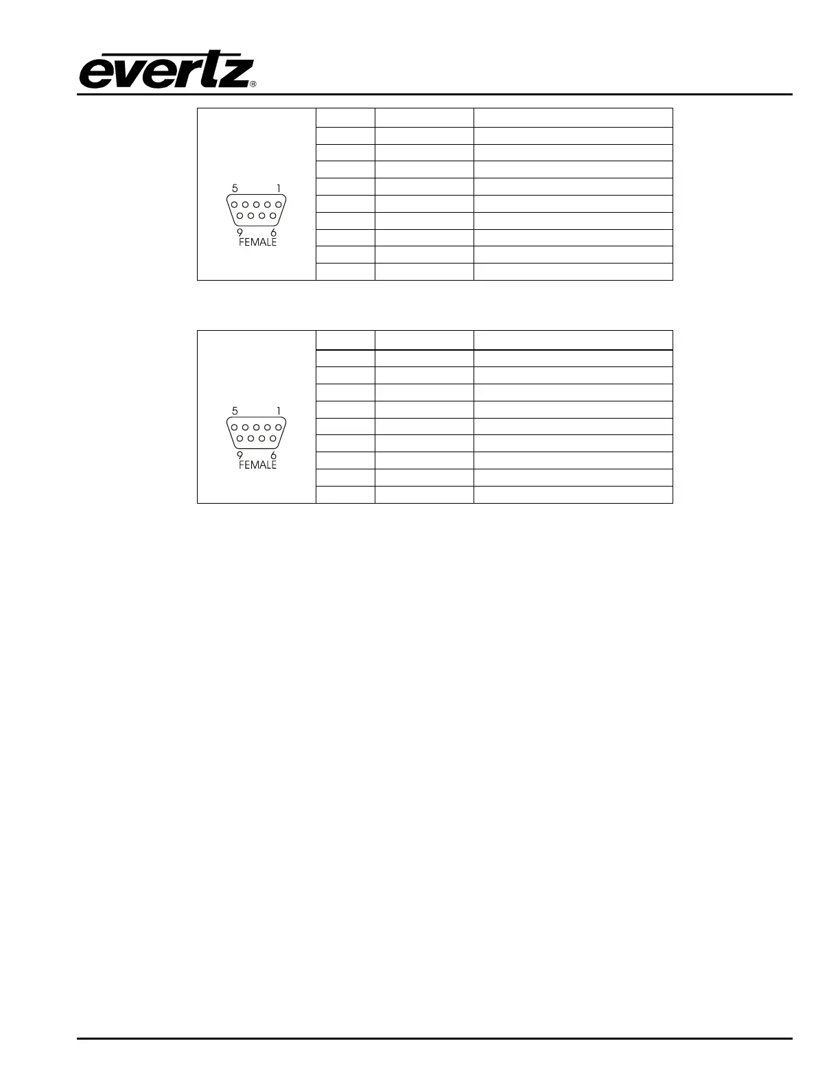
Pin # Name Description
1 GND Chassis
round
2 TxD RS-232 Transmit Output
3 RxD RS-232 Receive Input
4
5 Sig Gnd RS-232 Signal Ground
6
7 RTS
RS-232 RTS Input
8 CTS
RS-232 CTS Output
9
Table 2-1: Router RS-232 Port Pin Definitions
Pin # Name Description
1
2 Tx- RS-422 Tx- Output
3 Rx- RS-422 Rx- Input
4
5 GND
6
7 Tx+ RS-422 Tx+ Output
8 Rx+ RS-422 Rx- Input
Table 2-2: Router RS-422 Port Pin Definitions
2.5.2. Ethernet Network Connections
There are two RJ-45 Ethernet ports used for redundant connections to an Ethernet network. In order to
use both Ethernet connections the router frame must be fitted with two XRF6-FC Frame controller cards.
Connect the Ethernet cable described below to the RJ-45 connector on the side of the frame where your
XRF6-FC frame controller card is installed. If the frame is fitted with two frame controller cards then you
will have to provide an Ethernet connection to each RJ-45 connector in order to commicate with both
frame controllers.
The router is designed to be used with either 10Base-T (10 Mbps) or 100Base-TX (100 Mbps) also known
as
Fast Ethernet, twisted pair Ethernet cabling systems. When connecting for 10Base-T systems,
category 3, 4, or 5 UTP cable as well as EIA/TIA – 568 100
Ω STP cable may be used. When connecting
for 100Base-TX systems, category 5 UTP cable is required. The cable must be “straight through” with a
RJ-45 connector at each end. Make the network connection by plugging one end of the cable into the RJ-
45 receptacle of the Base Station and the other end into a port of the supporting hub.
The straight-through RJ-45 cable can be purchased or can be constructed using the pinout information in
Table 2-3. A colour code wiring table is provided in Table 2-3 for the current RJ 45 standards (AT&T 258A
or EIA/TIA 258B colour coding shown). Also refer to the notes following the table for additional wiring
guide information.