XRF6 RF Router Manual
INSTALLATION Revision 1.0 Page 2-1
2. INSTALLATION
2.1. REAR PANEL
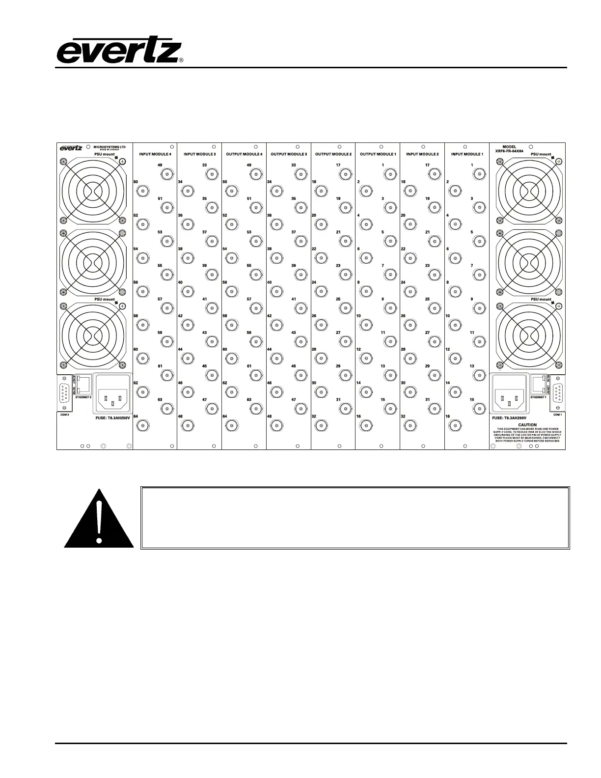
Figure 2-1: XRF6-FR Rear Panel Layout
If equipment connected to the router outputs supplies DC via coax (e.g. LNB
supply voltage), this DC MUST be turned off or otherwise blocked. Damage to
the router can result if DC is applied to the RF output ports.
2.2. MOUNTING
The Router frame is equipped with rack mounting rails and fits into a standard 19” x 10.5” x 20” rack space
(483 mm x 260 mm x 510 mm). To securely fasten the frame to the equipment rack, make sure that all
four mounting screws on each mounting rail are tightened securely.
After the unit has been installed in a rack, all cards in the frame should be checked to ensure they are fully
seated within the frame. This is best accomplished by simply pushing (simultaneously, with moderate
force) on each card’s top and bottom insertion/extraction levers. This step should be repeated any time
the frame is shipped, or relocated within a facility.