XRF6 RF Router Manual
CARD EDGE CONFIGURATION Revision 1.0 Page 4-1
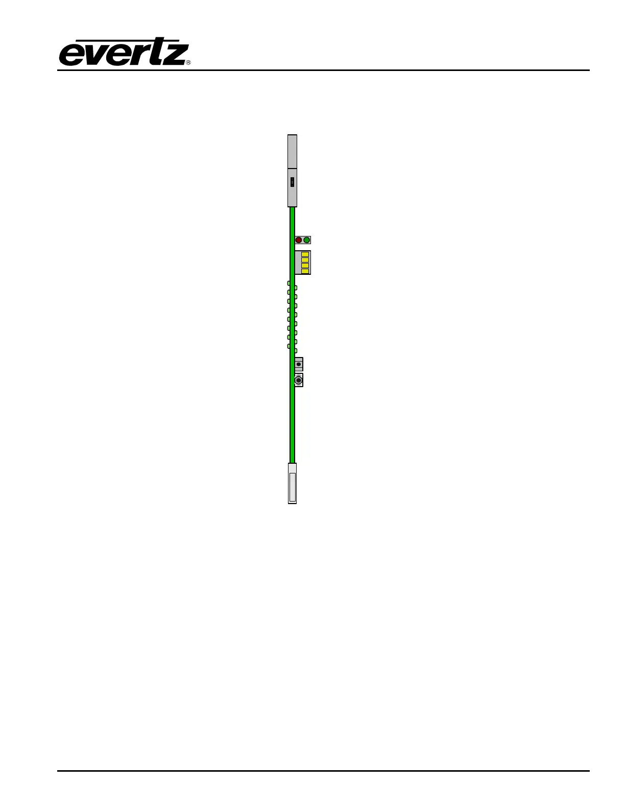
4. ROUTER CONFIGURATION USING THE INPUT CARD EDGE INTERFACE
XRF6-I16LB
4-Character
LED Display
Pushbutton
Toggle Switch
Figure 4-1: Input card edge controls
The input cards within the frame have a card edge mounted interface for configuration and status. This
interface consists of a pushbutton switch, a toggle switch, and a 4-character display. It can be used to
access the settings that are specific to each input card. These settings can also be accessed via the
frame controller serial port, as described in Chapter 3.
4.1. INPUT CARD EDGE INTERFACE OPERATION
The input card edge interface is used to navigate through the configuration and status menus on the input
card. Refer to Table 4-1 for the complete input card menu. Switch functions are indicated below:
Pushbutton: Selects the item shown in the 4-character display, and moves down (or back) one level in
the menu tree.
Toggle Switch: Moves between all menu items within the current menu level