XRF6 RF Router Manual
Page 5-2 Revision 1.0 STATUS LEDS
5.1.3. Input Card LEDs
XRF6-I16LB
4-Character
LED Display
Inupt 1
Input 2
Input 3
Input 4
Input 5
Input 7
Input 9
Input 11
Input 13
Input 15
Input 6
Input 8
Input 10
Input 12
Input 14
Input 16
Pushbutton
Toggle Switch
Green: Board Active
Green: RF input OK
Red: RF input level too high
Yellow: RF input level low
Off: RF input squelched
Red: Fault
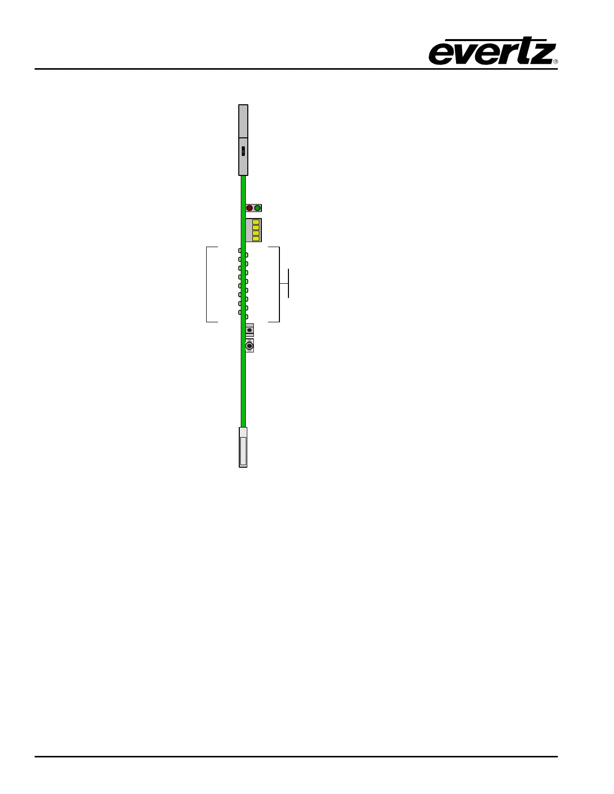
Figure 5-2: Input card LED Indicators
The input card has several edge-mounted LEDs that are used for configuration and status indication. The
red and green LED pair located near the top of the board indicate overall board health status. The green
LED indicates that the input card has established communication with the frame controller. The red LED
indicates a card fault.
The 4 character LED display is used in conjuction with the pushbutton and toggle switch. Together they
comprise the card edge interface for input card configuration (described in section 4.1).
The 16 multicolour LEDs indicate the status of the RF input at each of the 16 inputs on the card. Green
indicates an RF signal is present and within acceptable power limits. Red indicates that the RF input
power is too high, yellow indicates RF power is too low. An LED that is not illuminated indicates that the
RF input signal (if any) is below the user adjustable input squelch threshold.