Table 26: Pinouts for the DB-9 Console Connector (continued)
Function Pin Number Direction
RTS (request to send) 7 Out
CTS (clear to send) 8 In
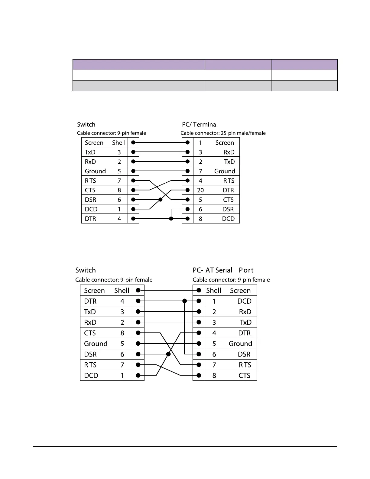
Figure 52 shows the pinouts for a 9-pin to 25-pin (RS-232) null-modem cable.
Figure 52: Null-Modem Cable Pinouts
Figure 53 shows the pinouts for a 9-pin to 9-pin (PC-AT) null-modem serial cable.
Figure 53: PC-AT Serial Null-modem Cable Pinouts
Technical Specications Console Connector Pinouts
ExtremeSwitching 5420 Series Hardware Installation Guide 111
 Loading...

