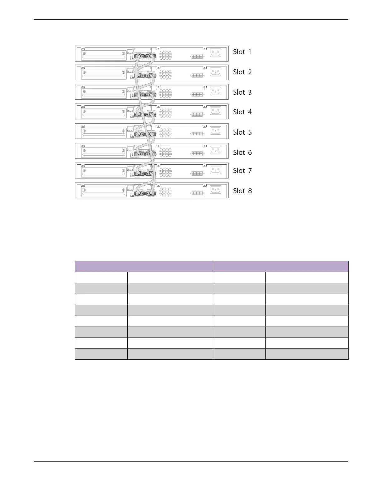
Figure 41: SummitStack Cable Connections Using Eight Switches with Integrated
SummitStack Ports
Table 17 lists the recommended order for connecting the stacking ports in this
example.
Table 17: Basic Stack with Eight Switches: Connections
Connect this slot and port . . . . . . To this slot and port
Slot 1 Stack Port 2 Slot 2 Stack Port 1
Slot 2 Stack Port 2 Slot 3 Stack Port 1
Slot 3 Stack Port 2 Slot 4 Stack Port 1
Slot 4 Stack Port 2 Slot 5 Stack Port 1
Slot 5 Stack Port 2 Slot 6 Stack Port 1
Slot 6 Stack Port 2 Slot 7 Stack Port 1
Slot 7 Stack Port 2 Slot 8 Stack Port 1
Slot 8 Stack Port 2 Slot 1 Stack Port 1
Example: Stacked Switches across Several Racks
Figure 42 shows ve switches installed at the tops of ve adjacent racks. To
accommodate the shortest possible cables, immediately adjacent switches are not
always connected together. Port 2 on one switch is connected to Port 1 on the next
connected switch. If the easy setup feature is used to congure the stack parameters,
the assigned slot numbers will be as shown in the gure.
Build Stacks Connect the Switches to Form the Stack Ring
ExtremeSwitching 5420 Series Hardware Installation Guide 71
 Loading...

