Chapter 1: Summit Family Switches
Summit Family Switches Hardware Installation Guide
60
Figure 36: Summit X440-24t Switch Rear Panel
Summit X440-L2-24t Switch
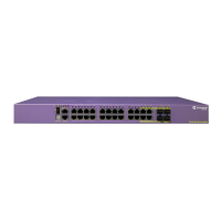
The front panel of the Summit X440-L2-24t switch (Figure 37) includes:
● Twenty-four fixed autosensing 10/100/1000BASE-T ports (ports 1–24) that provide 24 Gbps of
high-density copper connectivity
● Four unpopulated SFP ports (ports 21–24) that provide 4 Gbps of fiber connectivity. The SFP ports
support both 100BASE-FX and 1000BASE-X optical modules.
Ports 21 through 24 are implemented as shared ports that pair a copper port with a fiber port. For
more information about combination ports, see “Combination Ports and Failover” on page 22.
For information about SFPs, see the Extreme Networks Pluggable Interface Modules Installation Guide.
● Ethernet management port
● Serial console port implemented as an RJ-45 connector, used to connect a terminal and perform local
management
● LEDs to indicate port status and switch operating conditions
For a description of the LEDs and their operation, see “Summit X440 Series Switch LEDs” on
page 77.
Figure 37: Summit X440-L2-24t Switch Front Panel
The rear panel of the Summit X440-L2-24t switch (Figure 36) includes:
● Redundant power input connector for optional connection to the EPS-C2 External Power Module
The connecting redundant power supply cable is shipped with the power module unit. See
“Installing an EPS-C2 Chassis” on page 322 for more information.
3
SH_264
2
1
1 = AC power input connector
2 = Stacking ports
3 = Redundant power connector
X440-L2-24t
SH_263L
4 5
321
1 = Ethernet management port
2 = 10/100/1000BASE-T ports
3 = SFP ports
4 = Console port
5 = Combination ports
 Loading...