Chapter 1: Summit Family Switches
Summit Family Switches Hardware Installation Guide
82
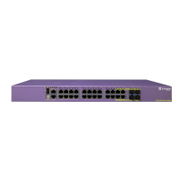
Summit X450-24x Switch
The front panel of the Summit X450-24x switch (Figure 61) includes:
● Twenty fixed SFP ports (ports 5–24) that provide 20 Gbps of high-density fiber connectivity
For information about SFPS, see the Extreme Networks Pluggable Interface Modules Installation Guide.
● Four combination ports (ports 1–4) using RJ-45 connectors and SFPs to provide 4 Gbps of copper or
fiber connectivity
For more information about combination ports, see “Combination Ports and Failover” on page 22.
● LEDs to indicate port status and switch operating conditions
For a description of the LEDs and their operation, see “Summit X450, X450a, and X450e Series
Switch LEDs” on page 105.
● Stack number indicator showing the position of this switch in a stacked configuration
● Serial console port used to connect a terminal and perform local management
Figure 61: Summit X450-24x Switch Front Panel
The rear panel of the Summit X450-24x switch (Figure 62) includes:
● Slot for the Summit XGM-2xn option card, which allows you to add one or two 10-gigabit XENPAK
modules
See “Summit XGM-2xn Option Card” on page 159.
● Management port with associated LEDs
● Two high-performance stacking ports with associated LEDs
● Redundant power input connector for optional connection to the EPS-160 External Power Module
(Model No. 10907).
The connecting redundant power supply cable is shipped with the EPS-160 unit. See “EPS-160
External Power Module (with EPS-T)” on page 140 for more information.
● AC power input socket
The internal power supply operates from 100 VAC to 240 VAC.
Figure 62: Summit X450-24x Switch Rear Panel
STACK NO.
Band On = Link
Blinking = Activity
Shared Ports
S450_001D
10/100/1000 Mbps ports
Console
port
Mini-GBIC ports
Combination ports
Stack number
indicator
10 Gigabit
uplink option
Management port
10 Gigabit
stacking ports
Power socket
External power
supply connection
 Loading...