IN1608 xi Scaling Presentation Switcher • Installation 18
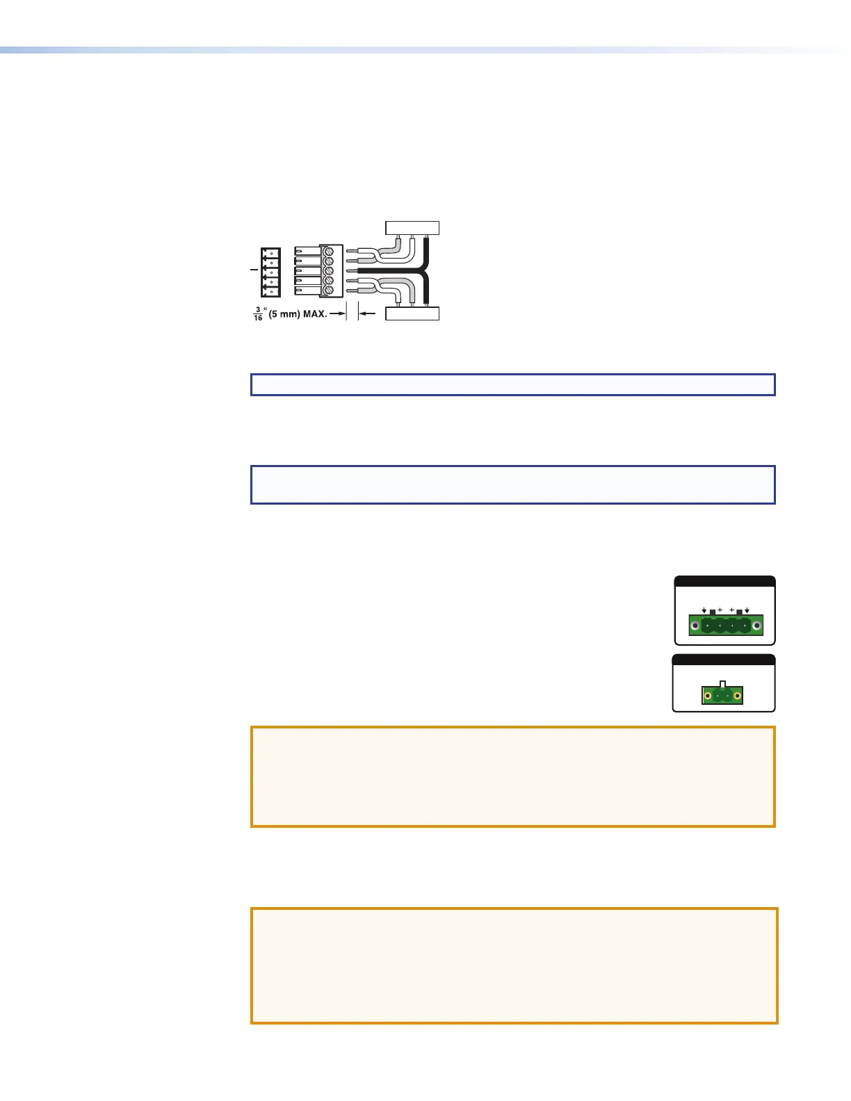
RS-232 Over TP port — To pass bidirectional serial control, connect a control device
to the 5-pole captive screw connector. This port consists of the three poles labeled
“RS-232” and shares the ground pole with the IR port.
IR Over TP port — To transmit and receive IR signals, connect a control device to the
5-pole captive screw connector. This port consists of the two poles labeled “IR” and
shares the ground pole with the RS-232 port.
Tx/Rx
Pins
RxTx
RS-232
RxTx
TxRx
RxTx
G
G
G
IR
Figure 12. RS-232 and IR Over TP Wiring
NOTE: RS-232 and IR data can be transmitted simultaneously.
B
HDMI output connectors — Connect HDMI display devices to these connectors.
Use either of the connectors for a local monitor to display the On-screen Display (OSD)
menu (see Operation on page 25).
TIP: Use Extron HDMI LockIt Lacing Brackets to secure HDMI cables to the device
(see HDMI Connections on page 22).
C
Analog audio output connectors — Connect audio output devices to these 5-pole
captive screw connectors. Wire the connector for line level, balanced or unbalanced,
analog stereo (see Analog Audio Connection on page 21).
D
Amplified Output —
Stereo audio models — Connect unpowered, 4-ohm or 8-ohm
speakers to this 4-pole 5 mm captive screw connector to play
amplified stereo audio from the Amplified Output.
Mono audio models — Connect unpowered, high impedance
speakers to this 2-pole captive screw connector to play the amplified
mono audio from the Amplified Output.
ATTENTION:
• Ensure the rated input voltage of the speakers matches the rated output
voltage of the switcher.
• Assurez-vous que la tension nominale d’entrée des enceintes soit compatible
avec la tension nominale de sortie du sélecteur.
E
TP output mode selection switch — This toggle switch lets you select between DTP
(default) and HDBaseT modes for the twisted pair output. Set the switch to the down
position to select DTP (which also enables +12 V remote power). For HDBT, set the
switch to up (remote power is disabled).
ATTENTION:
• Position this switch before connecting the appropriate device to the DTP
connector. Failure to comply can damage the endpoint.
• Positionnez le sélecteur avant de connecter l’appareil approprié au connecteur
DTP. Ne pas respecter cette procédure poutrait endommager le point de
connexion.
2x25W(8Ω)/2x50W(4Ω)
L
R
CLASS 2 WIRING
AMPLIFIED OUTPUT
70V - 100W
CLASS 2 WIRING
+
-

 Loading...