IN1608 xi Scaling Presentation Switcher • Installation 23
Serial and IR Insertion Connections
100-240V ~ -- A MAX
1
2
CONFIGURABLE
HDMI
HDMI
5
6
7
8
1C
RS-232 IR
RS-232 IR
Tx Rx Tx RxG
Tx Rx Tx RxG
Tx Rx Tx RxG
HDMI
1A
1B
3
4
INPUTS
OUTPUTS
Tx Rx
RS-232
G
LAN
2x25W(8Ω)/2x50W(4Ω)
RESET
AUDIO INPUTS
OUTPUTS
REMOTE
LL1R R
L2
R
L
3
R
CLASS 2 WIRING
L4
R
L5R
+48V
+48V
12
LR
VARIABLE
IN1608 SA
2
MIC/LINE
L6
R
SIG LINK
DTP IN
SIG LINK
DTP IN
SIG LINK
DTP OUT
50/60 Hz
RS-232 IR
OVER DTP
OVER DTP
OVER DTP
AMPLIFIED OUTPUT
A
B
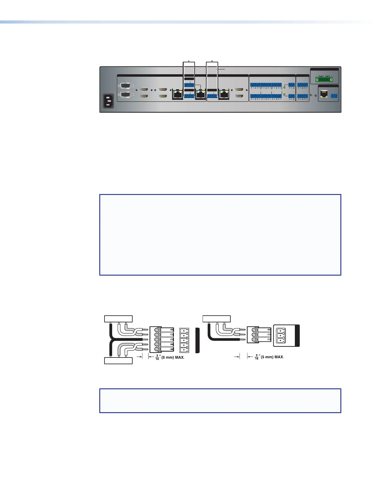
Figure 19. Serial and IR Insertion Connections
A
Over TP (inputs 7 and 8) ports — If desired, connect serial RS-232 signals,
modulated IR signals, or both to these 3.5 mm, 5-pole captive screw connectors to
insert bidirectional RS-232 and IR communications onto the associated inputs (see
“Serial and IR port connectors” to wire the cables).
B
Over TP (output 1C) port — If desired, connect a serial RS-232 signal, modulated IR
signal, or both to this 3.5 mm, 5-pole captive screw connector to insert bidirectional
RS-232 and IR communications onto the associated output (see “Serial and IR port
connectors” to wire the cables).
NOTE: These ports enable you to insert RS-232 control signals onto the same cable
that carries video and audio to extend them to the Over TP port of a connected
endpoint. The control signals can be inserted two ways:
• Ethernet to RS-232 insertion (see Ethernet to RS-232 Insertion on page 44),
in which a control signal applied to an IN1608 xi LAN port can be routed to the
RS-232 port of any connected twisted pair device.
• Captive screw insertion (see Captive Screw Signal Insertion on page 46), in
which a control signal applied to an RS-232 captive screw port is tied directly to the
same-numbered TP port (RS-232 input port 7 is tied to TP port 7 only, and 8 is tied
to 8).
Serial and IR port connectors
Figure 20 shows how to wire the Over DTP RS-232 and IR and Remote connectors.
Tx/Rx
Pins
Rx Tx
Tx Rx
Gnd
Gnd
RS-232 IR
Tx Rx Tx RxG
OVER TP
TxGnd
Rx
Tx Rx G
REMOTE
Figure 20. RS-232 and IR Connectors Wiring
NOTE: The length of the exposed wires is important. The ideal length is 3/16 inch
(5 mm) (see the audio input connector ATTENTION notifications on the previous page
for details).

 Loading...