IN1608 xi Scaling Presentation Switcher • Installation 19
Control Connections
100-240V ~ -- A MAX
1
2
CONFIGURABLE
HDMI
HDMI
5
6
7
8
C
RS-232 IR
RS-232 IR
Tx Rx Tx RxG
Tx Rx Tx RxG
Tx Rx Tx RxG
HDMI
A
B
3
4
INPUTS
OUTPUTS
Tx Rx
RS-232
G
LAN
2x25W(8Ω)/2x50W(4Ω)
RESET
AUDIO INPUTS
OUTPUTS
REMOTE
LL1R R
L2
R
L
3
R
CLASS 2 WIRING
L4
R
L5R
+48V
+48V
12
LR
VARIABLE
IN1608 SA
2
MIC/LINE
L6
R
SIG LINK
DTP IN
SIG LINK
DTP IN
SIG LINK
DTP OUT
50/60 Hz
RS-232 IR
OVER DTP
OVER DTP
OVER DTP
AMPLIFIED OUTPUT
A
LAN connector
B
Remote RS-232 connector
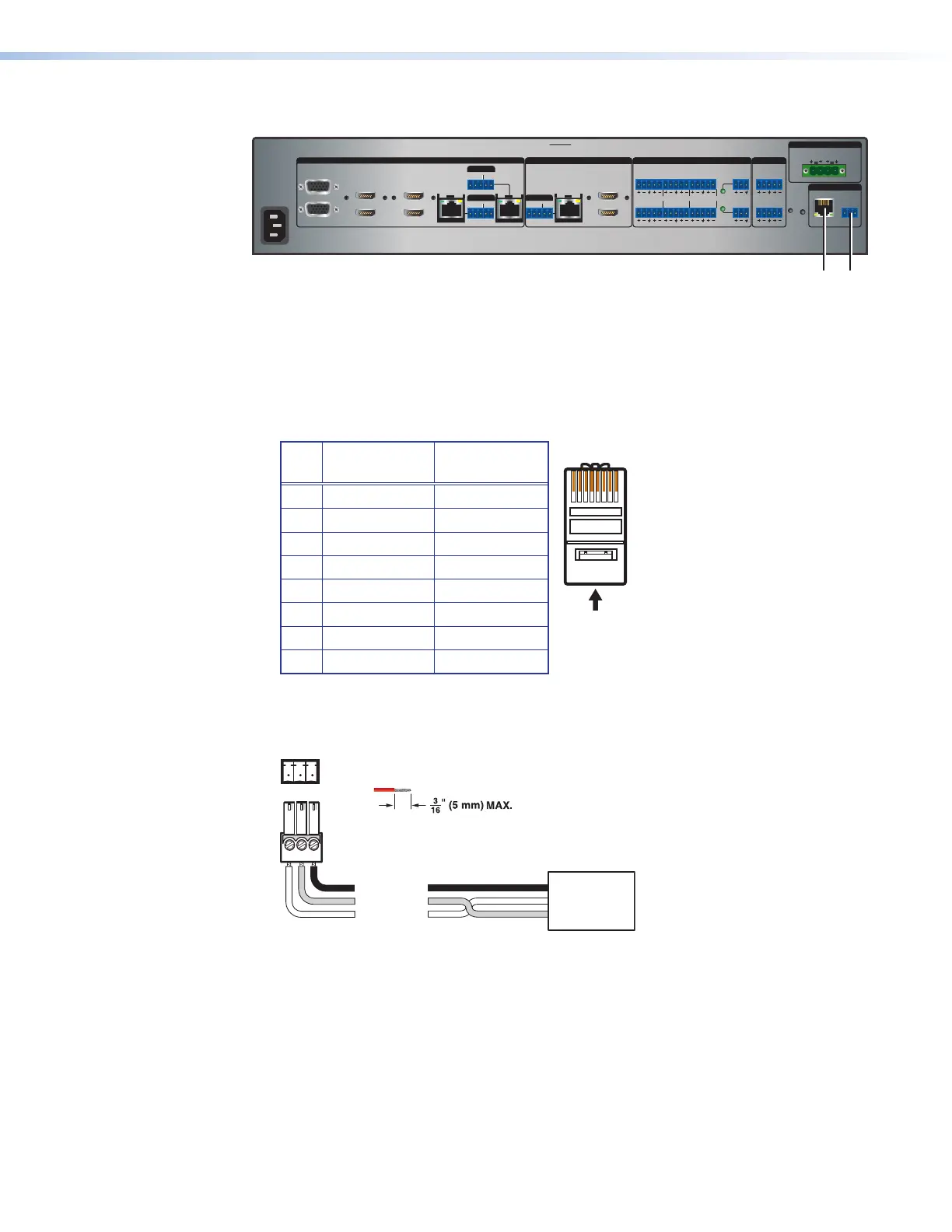
Figure 13. Control Connectors (IN1608 xi SA Example)
A
LAN connector — Connect a computer network to this RJ-45 connector. Use a patch
cable to connect to a switch, hub, or router. Wire the connector as shown below.
Pin T568A
Wire Color
T568B
Wire Color
1 White-green White-orange
2 Green Orange
3 White-orange White-green
4 Blue Blue
5 White-blue White-blue
6 Orange Green
7 White-brown White-brown
8 Brown Brown
LEDs on this connector indicate link and activity status.
B
Remote RS-232 connector — Connect a host device to this 3-pole captive screw
connector for RS-232 serial control. The default baud rate is 9600.
Do not tin the wires!
Controlling
Device
Ground (G)
Receive (Rx)
Transmit (Tx)
Ground (G)
Receive (Rx)
Transmit (Tx)
Bidirectional
Tx Rx G
Figure 14. RS-232 Wiring
12345678
RJ-45
t T
Pair Wires

 Loading...