4 Electrical installation
Festo – GDCP-CMMP-M0-HW-EN – 1511c – English 35
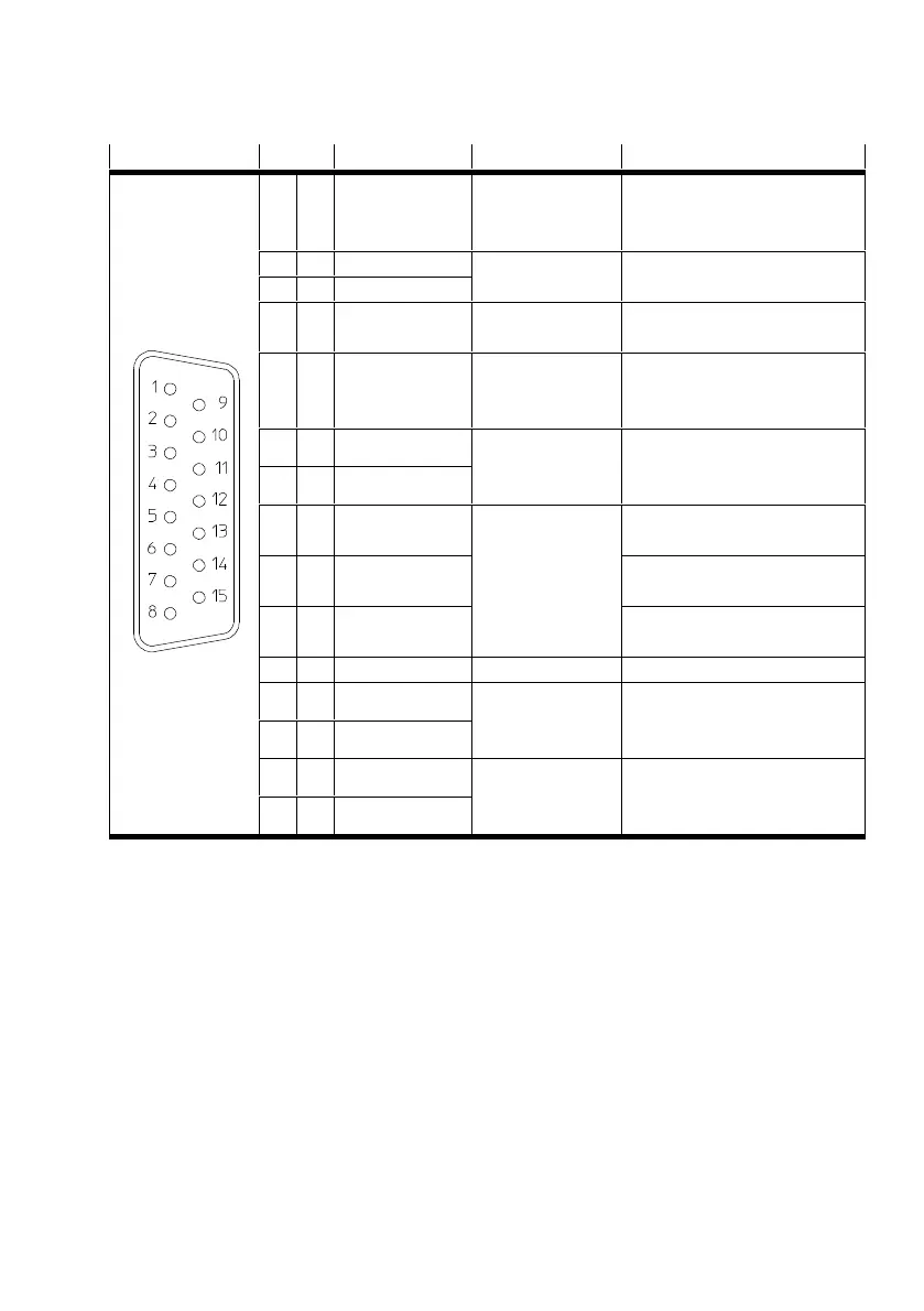
[X2B] Pin no. Designation Value Specification
1 MT+ +3.3 V R
i
= 2 kΩ Temperature sensor, motor
temperature, N/C contact, PTC,
KTY ...
9 U_SENS+ 5 V … 12 V
R
I
L 1 kΩ
Sensor cable for the encoder
supply
2 U_SENS-
10 US 5 V/12 V / ±10%
I
max
= 300 mA
Operating voltage for high-
resolution incremental encoder
3 GND 0V Reference potential for
encoder supply and motor
temperature sensor
11 N 2 V
SS
… 5 V
SS
R
I
L 120 Ω
Zero impulse RS422
(differential) from digital incre
ment generator
4 N#
12 H_U 0V/5V
R
I
L 2 kΩ
at VCC
Phase U Hall sensor for
commutation
5 H_V Phase V Hall sensor for
commutation
13 H_W Phase W Hall sensor for
commutation
6 –
14 A 2 V
SS
… 5 V
SS
R
I
L 120 Ω
A tracking signal RS422
(differential) from digital incre
mental encoder
7 A#
15 B 2 V
SS
… 5 V
SS
R
I
L 120 Ω
B tracking signal RS422
(differential) from digital incre
mental encoder
8 B#
Tab. 4.11 Pin assignment: Digital incremental encoder – optional
The outer screening must always be connected to the PE (plug housing) of the motor controller.
 Loading...


