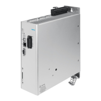
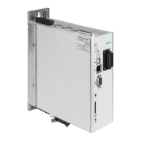
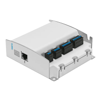
CMMP-AS-...-M0
4 Festo – GDCP-CMMP-M0-HW-EN – 1511c – English
4.5.2 Pin assignment [X2B] 33..............................................
4.6 Connection: CAN bus [X4] 36...................................................
4.6.1 Plug [X4] 36........................................................
4.6.2 Pin assignment [X4] 36...............................................
4.7 Connection: Motor [X6] 37.....................................................
4.7.1 Plug [X6] 37........................................................
4.7.2 Pin assignment [X6] 37...............................................
4.8 Connection: Voltage supply [X9] 39..............................................
4.8.1 Plug 39............................................................
4.8.2 Pin assignment [X9] – single-phase 39...................................
4.8.3 Pin assignment [X9] – triple-phase 40....................................
4.8.4 Mains fuse 41......................................................
4.8.5 AC supply 41.......................................................
4.8.6 Braking resistor 43..................................................
4.9 Connection: Incremental encoder input [X10] 44...................................
4.9.1 Plug [X10] 44.......................................................
4.9.2 Pin assignment [X10] 44..............................................
4.9.3 Type and design of the cable [X10] 45...................................
4.9.4 Connection instructions [X10] 45.......................................
4.10 Connection: Incremental encoder output [X11] 45..................................
4.10.1 Plug [X11] 45.......................................................
4.10.2 Pin assignment [X11] 45..............................................
4.11 FCT interfaces 46............................................................
4.11.1 Overview of interfaces 46.............................................
4.11.2 USB [X19] 46.......................................................
4.11.3 Ethernet TCP/IP [X18] 47..............................................
4.12 Connection: I/O interface for STO [X40] 49........................................
4.12.1 Plug [X40] 49.......................................................
4.12.2 Pin assignment [X40] 49..............................................
4.12.3 Circuitry with use of the STO safety function [X40] 49.......................
4.12.4 Circuitry without use of the STO safety function [X40] 49....................
4.13 Instructions on safe and EMC-compliant installation 51..............................
4.13.1 Explanations and terms 51............................................
4.13.2 General remarks on EMC 51...........................................
4.13.3 EMC areas: First and second environment 52..............................
4.13.4 EMC-compliant wiring 53.............................................
4.13.5 Operation with long motor cables 55....................................
4.13.6 ESD protection 55...................................................
5 Commissioning 56...........................................................
5.1 General connection instructions 56..............................................
5.2 Tools / material 56...........................................................
5.3 Connecting the motor 56......................................................

 Loading...


