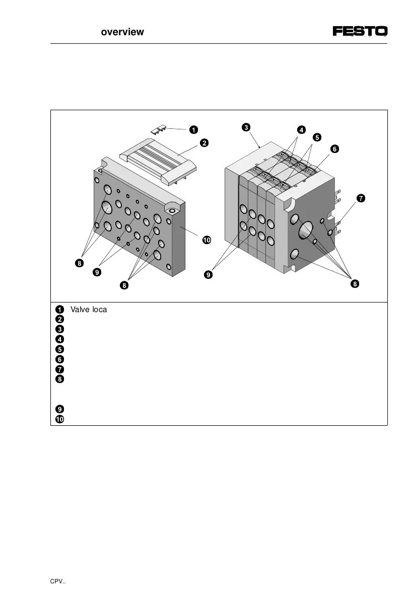
On the CP valve terminal you will find the following
pneumatic connections and operating elements:
1
2
3
4
5
6
7
8
9
0
Valve location inscription clip (per valve)
Support for inscription clip and cover of manual override
Type plate
Manual override (per pilot solenoid, pushing or locking)
Clip of pushing manual override
Recess for label support
Earth/ground connection (left/right-hand end plate)
Supply connections (1, 11, 12/14), exhaust connections (3/5, 82/84):
with individual tubing on left and/or right-hand end plate
with central tubing on pneumatic multiple connector plate
Work connections (2, 4), per valve
Pneumatic multiple connector plate
Fig. 1/4: Pneumatic connections and operating elements on the
CP valve terminal
8
9
8
0
2
1
3
4
5
6
7
9
1. System overview
CPV... 9802 1-11
 Loading...