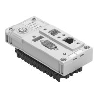
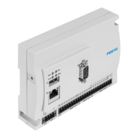
• Place the CP terminal on the right-hand end plate.
Make sure that the tie rod, which has not yet been
tightened, does not fall out of the CP terminal.
• Remove the left-hand end plate from the CP termi-
nal.
• Place the left-hand end plate on the CP terminal.
Swing the CP terminal onto the left-hand end plate.
• Screw in the tie rod and tighten it with 0.3 Nm.
• Then tighten first the centre and then the outer tie
rod with 2 Nm (CPV10/14) or with 4 Nm (CPV18).
• In the case of CP valve terminals with CP, AS-i or
MP connections, fit the appropriate connector plate
(see section "Fitting components onto valve locations").
• Fit the CP terminals onto their fastening surfaces
(see sections "Fitting onto a wall", "Fitting onto a hat
rail" or "Fitting with feet" in the chapter "Fitting").
• Finally connect the pneumatic tubing and the electri-
cal cables (see chapter "Installation").
5. Maintenance and conversion
CPV... 9802 5-17
 Loading...

