Symbol Description
[di.] Activation/deactivation of the numerical display
Switching off the display backlight
[PnP]/[nPn] Switching the switching output
[P2-] Allocation of the switching output for Pin 2 with the binary signal OutB or OutC
[P4-] Allocation of the switching output Pin 4 with the binary signal OutA or OutC
[rP.] Replicate settings to another device
[F.] Set Analog output filter time τ for analogue output
[0..10]/[1.. 5] Switching the voltage output
[H.] Scaling the analogue output end value
[L.] Scaling the analogue output start value
[----] Numerical display is switched off
[IOL] Flashes 3x when Edit mode is blocked by IO-Link
[SUP.P] Error message: supply pressure is outside the set limits (SP
min
/SP
max
)
[CLER] Device has been reset to factory settings
Graphic display of the current distance-correlated value for InA and InB in relation
to the set switching point
– The bar graph for InA is always active.
– The bar graph for InB is only active if the binary signal OutB is assigned to the
switching output at Pin 2.
1) "A" flashes when IO-Link communication is active
Tab. 2 Symbols on the display
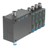
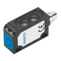
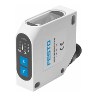
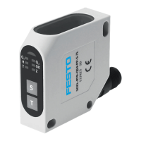
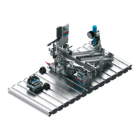
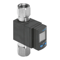
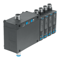
Product overview
10 Festo — SOPA — 2020-04