5 Product overview
5.1 Configuration
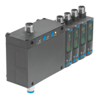
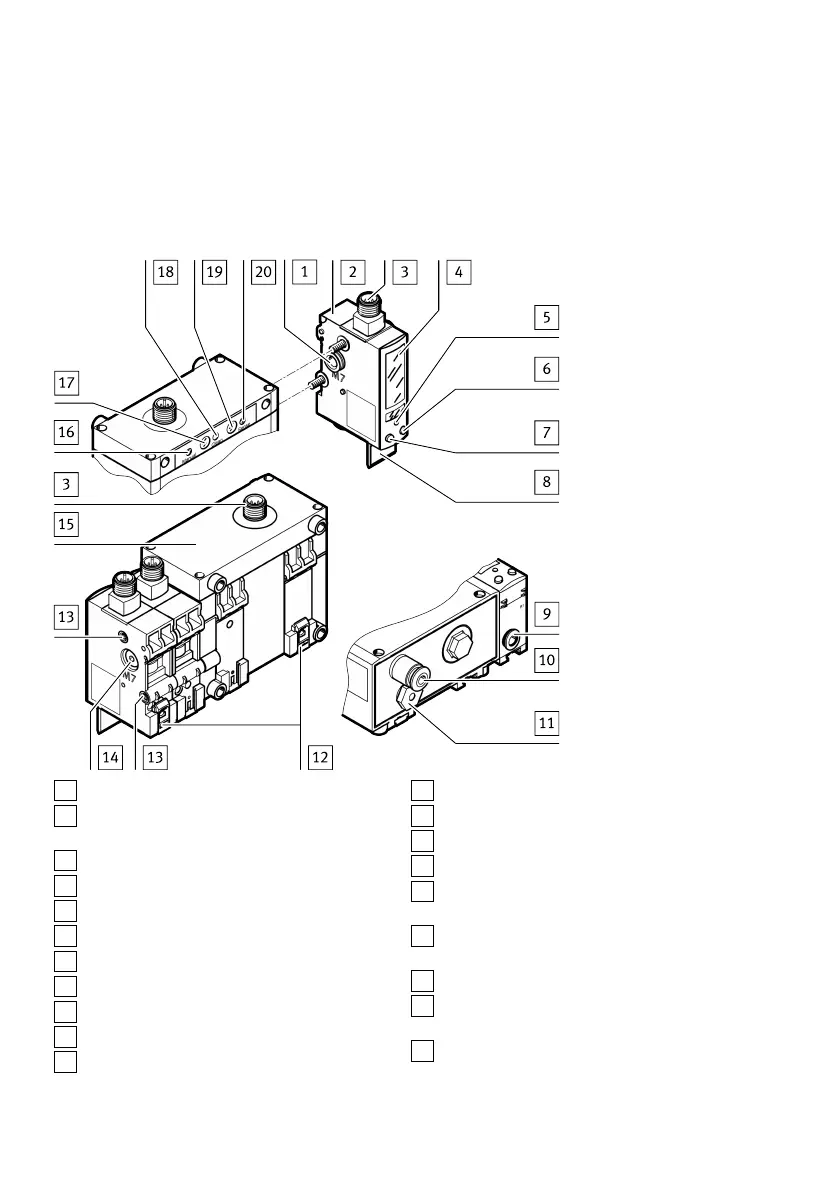
5.1.1 Product design
1
Supply port for supply pressure
2
Sensor module (max. 4 modules permitted
in combination with control module)
3
Plug for electrical connection
4
Display
5
Edit button
6
B pushbutton
7
A pushbutton
8
Label holder
9
Pneumatic port for measuring nozzle (outlet)
10
Supply port for operating pressure
11
Vent screw (width across flats 14)
12
Mounting slides
13
Threaded sleeve (M4)
14
Blanking plug (M7)
15
Control module (optional)
16
Manual LED (green) – ready indication for
manual override (SOPA-C..-H only)
17
Clean pushbutton (blow-out air) (SOPA-C..-H
only)
18
Status LED (yellow) – clean (blow-out air)
19
Sense pushbutton (measuring air)
(SOPA-C..-H only)
20
Status LED (yellow) – sense (measuring air)
Fig. 1 Product design
Product overview
8 Festo — SOPA — 2020-04