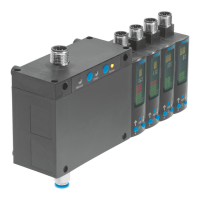
switching measuring and exhaust air. Up to 4sensor modules contain the sensory functions. The
sensor modules can be operated both individually and in combination with the control module.
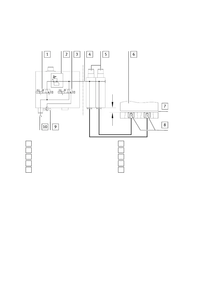
1
3/2-way valve (instrument air)
2
Pressure regulator
3
3/2-way valve (exhaust air)
4
Supply pressure
5
Sensor modules (pneumatically linked)
6
Object (example)
7
Air gap
8
Measuring nozzles (1 per sensor module)
9
Vent screw
10
Supply port for operating pressure
Fig. 6 Configuration with a control module and two sensor modules
The compressed air flows from the sensor modules to the measuring nozzles. If the object is very close
to a measuring nozzle, the air gap is very small and only a small amount of air flows through. As the
object gets further away, the air gap becomes larger and more air flows through. The change in flow
rate is detected by the sensor modules, converted into a distance-correlated value and displayed
(speed measuring method with ejector).
5.2.4 Analogue output
Analogue output
The analogue output (distance monitoring) is available as voltage output 0…10V or 1…5V or as
current output 4…20mA.
Scaling of the analogue output
The analogue output at pin 2 of the electrical connection can be scaled. In the delivery status the out-
put characteristic curve at its end points (0…10V or 1…5V or 4…20mA) is allocated to the value
0…300 displayed correlated to the distance.
To scale the output characteristic curve, the effective range can be adapted for the distance input vari-
able è Tab. 7. The scaling of the analogue signal means that only a limited sensing range affects the
entire stroke of the analogue output (zoom function). This zoom function can be used to improve the
resolution of the analogue output.
Product overview
15Festo — SOPA — 2020-04