SOPA -...- PNLK
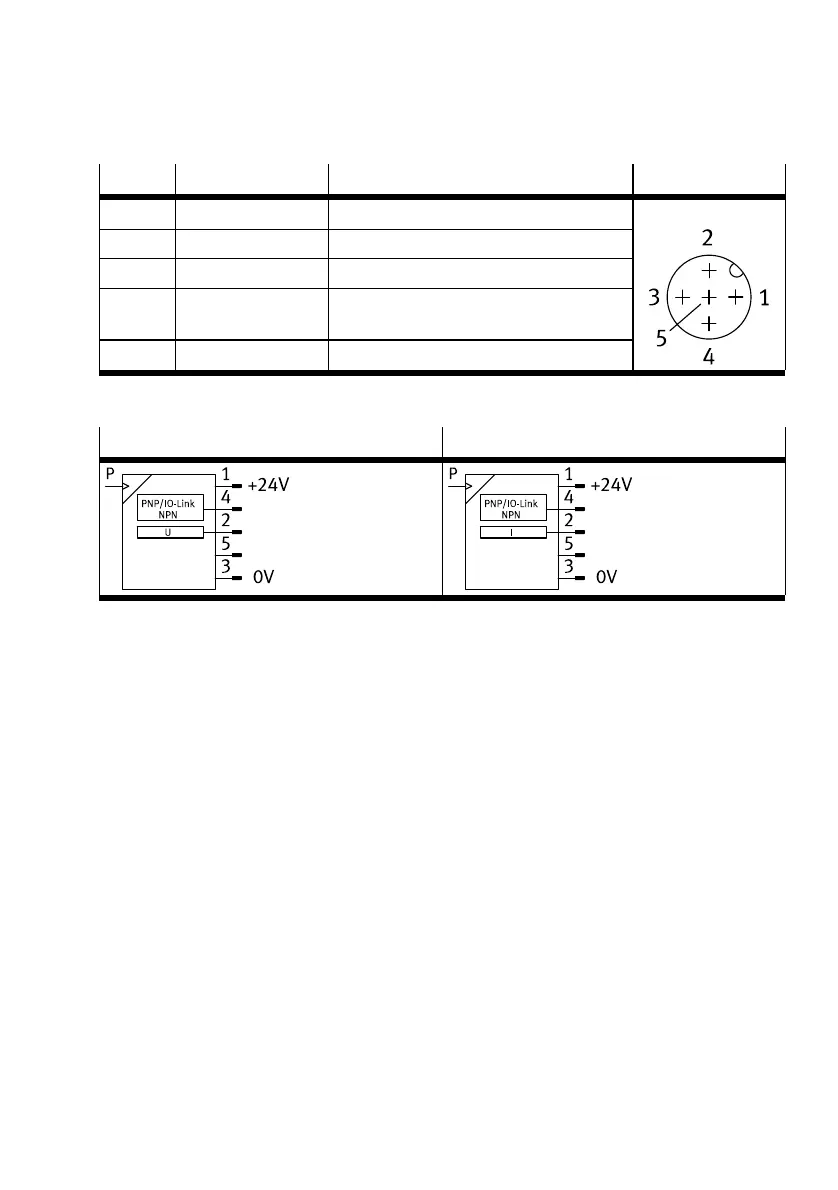
Pin Wire colour
1)
Allocation Plug
1 Brown (BN) Operating voltage +24VDC
2 White (WH) Analogue output
3 Blue (BU) Operating voltage 0V
4 Black (BK) Switching output for OutA or OutC (C/Q line
with IO-Link)
5 Grey (GY) n.c = free (not connected)
M12, 5-pin
1) When using the connecting cable from the accessories.
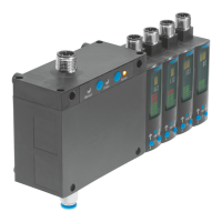
Tab. 15 Pin allocation for sensor module
SOPA-...-PNLK-VB-... SOPA-...-PNLK-A-...
Tab. 16 Circuit diagrams for sensor module
8 Commissioning
8.1 Displaying parameters (INFO/SHOW mode)
Requirement: the sensor is ready for operation (RUN mode).
1. Press A pushbutton, B pushbutton or A and B pushbutton.
Ä
Display shows the relevant input value or an error number.
2. To display each of the following parameters, press the A pushbutton, B pushbutton or A and B
pushbutton è Fig.18.
3. At the end of the SHOW mode, the relevant minimum and maximum values are displayed. To reset
the display of the minimum and maximum values, press the Edit button.
Ä
RUN mode is active.
Commissioning
25Festo — SOPA — 2020-04