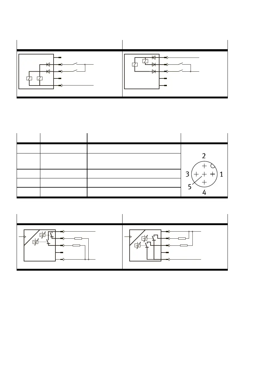
SOPA-C..-...-...-2P-...
1)
SOPA-C-...-2N-...
BK
BU
+24 V
0 V
WH
PNP
1
4
3
2
5
SenseClean
BN
BK
+24 V
0 V
WH
NPN
1
4
3
2
5
Sense
Clean
1) in combination with PNLK sensor modules
Tab. 12 Circuit diagrams for control module without manual override
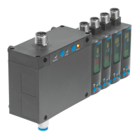
7.2.2 PIN allocation and sensor module circuit diagrams
SOPA-...-2P/-2N
Pin Wire colour
1)
Allocation Plug
1 Brown (BN) Operating voltage +24VDC
2 White (WH) Switching output for OutB or OutC (factory
setting)
3 Blue (BU) Operating voltage 0V
4 Black (BK) Switching output for OutA
5 Grey (GY) n.c = free (not connected)
M12, 5-pin
1) When using the connecting cable from the accessories.
Tab. 13 Pin allocation for sensor module
SOPA-...-2P-M12-... SOPA-...-2N-M12-...
BN
BK
BU
RL
+24 V
0 V
WH
P
RL
PNP
1
4
3
2
5
BN
BK
BU
+24 V
0 V
WH
P
NPN
1
4
3
2
5
RL
RL
Tab. 14 Circuit diagrams for sensor module
Installation
24 Festo — SOPA — 2020-04