Setting supply pressure monitoring for OutC
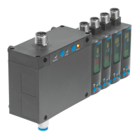
The binary signal OutC is pre-configured for monitoring the supply pressure with the control module
SOPA-C.
A change in the switching points only makes sense if a precision controller is used to operate the
sensor modules.
Requirement: EDIT mode is active.
1. Select [OutC] with the A or B pushbutton.
2. Press the Edit button to confirm the selection.
Ä
[SP min] flashes.
3. Set switching point (SP
min
) with the A or B pushbutton.
4. Press the Edit button to confirm the set value.
Ä
[SP max] flashes.
5. Set switching point (SP
max
) with the A or B pushbutton.
6. Press the Edit button to confirm the set value.
Ä
[NO] or [NC] flashes.
7. Select the switching element function with the A or B pushbutton.
8. Press the Edit button to confirm the selection.
Ä
RUN mode is active.
9. Use a test run to check that the sensor switches as desired (switching point and hysteresis).
10. Recommendation: after changing the switching points for OutC, re-teach the value for OutA.
8.4 Setting analogue output with…-PNLK-A (EDIT mode)
Requirement: EDIT mode is active.
1. Select [Analogue] with the A or B pushbutton.
2. Press the Edit button to confirm the selection of the output.
Ä
[F.] flashes.
3. Set end value of the display range of the scaling.
4. Press the Edit button to confirm the set value.
Ä
[H.] flashes.
5. Press the Edit button to confirm the set value.
Ä
[L.] flashes.
6. Set start value of the display range of the scaling.
7. Press the Edit button to confirm the set value.
Ä
RUN mode is active.
8.5 Setting analogue output with…-PNLK-VB (EDIT mode)
Requirement: EDIT mode is active.
1. Select [Analogue] with the A or B pushbutton.
2. Press the Edit button to confirm the selection of the output.
Ä
[F.] flashes.
3. Set time constant for low-pass filter with the A or B pushbutton.
Commissioning
29Festo — SOPA — 2020-04