7.2 Electrical installation
WARNING!
Risk of injury due to electric shock.
• For the electrical power supply, use only PELV circuits in accordance with IEC 60204-1/EN 60204-1
(Protective Extra-Low Voltage, PELV).
• Observe the general requirements of IEC 60204-1/EN60204-1 for PELV circuits.
• Only use voltage sources that ensure a reliable electric separation from the mains network in
accordance with IEC 60204-1/EN 60204-1.
1. Use signal lines that are shorter than 30m.
2. Configure binary outputs according to the wiring (only with PNLK sensor modules).
– Tightening torque for the union nut at the plug connector: 0.5Nm
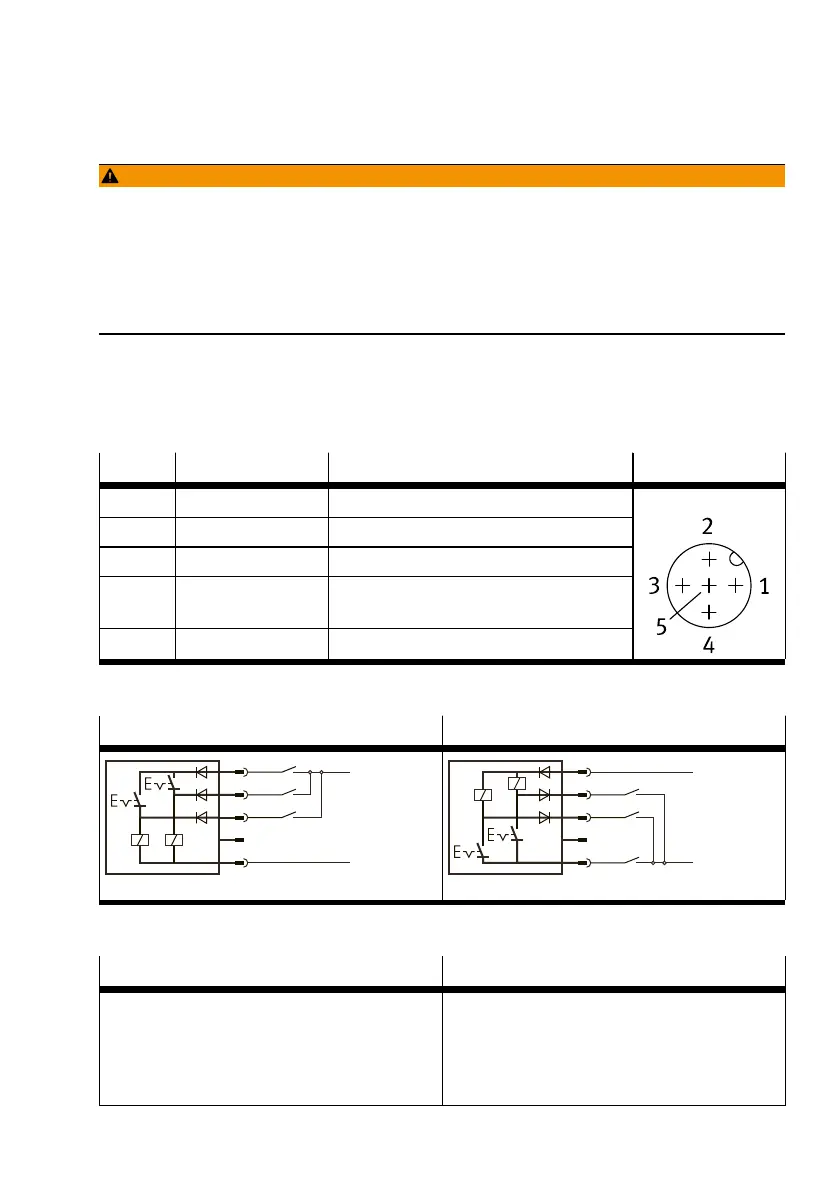
7.2.1 PIN allocation and control module circuit diagrams
Pin Wire colour
1)
Allocation Plug
1 Brown (BN) Operating voltage +24VDC
2 White (WH) Switch on signal input exhaust air (Clean)
3 Blue (BU) Operating voltage 0V
4 Black (BK) Switch on measuring air signal input
(Sense)
5 Grey (GY) n.c = free (not connected)
M12, 5-pin
1) When using the connecting cable from the accessories.
Tab. 10 Pin allocation for control module
SOPA-C..-H-...-2P-...
1)
SOPA-C..-H-...-2N-...
BN
BK
BU
+24 V
0 V
WH
PNP
1
4
3
2
5
Sense
Clean
BN
BK
BU
+24 V
0 V
WH
NPN
1
4
3
2
5
Sense
Clean
1) in combination with PNLK sensor modules
Tab. 11 Circuit diagrams for control module with manual override
SOPA-C..-...-...-2P-...
1)
SOPA-C-...-2N-...
Installation
23Festo — SOPA — 2020-04