1
Measuring nozzle
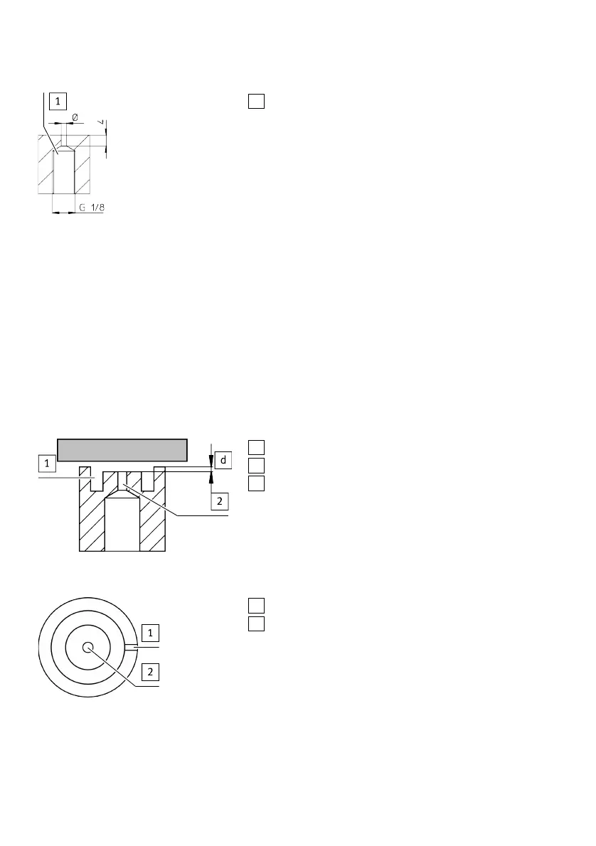
Fig. 7 Measuring Nozzle Geometry
1. Take the measuring nozzle geometry into account.
– Diameter: 1.5mm / 2.0mm (nominal diameter) / 2.5mm
2. Execute the outlet of the nozzle with sharp edges. Sharp edges at the outlet opening are permiss-
ible.
Measuring Nozzle Configuration
1. Ensure air outlet.
In the event of gap distance queries of < 30μm, it may be necessary to reset the outlet openings
of the nozzles by 30…60μm after the bearing surface in order to permit air discharge. The bear-
ing surface, in which the measuring nozzles are mounted, must be provided with ducts that permit
exhaust to the outside.
2. Comply with permissible tube lengths between the sensor module and measuring nozzle .
d
Distance 30… 60 μm
1
Air duct (example)
2
Measuring nozzle
Fig. 8 Recessed measuring nozzle
1
Air duct (example)
2
Measuring nozzle
Fig. 9 Exhausting
Assembly
18 Festo — SOPA — 2020-04