Installation Instructions
30.10.12 Kapitel/Chapter 6: Installation Instructions Seite/Page 81
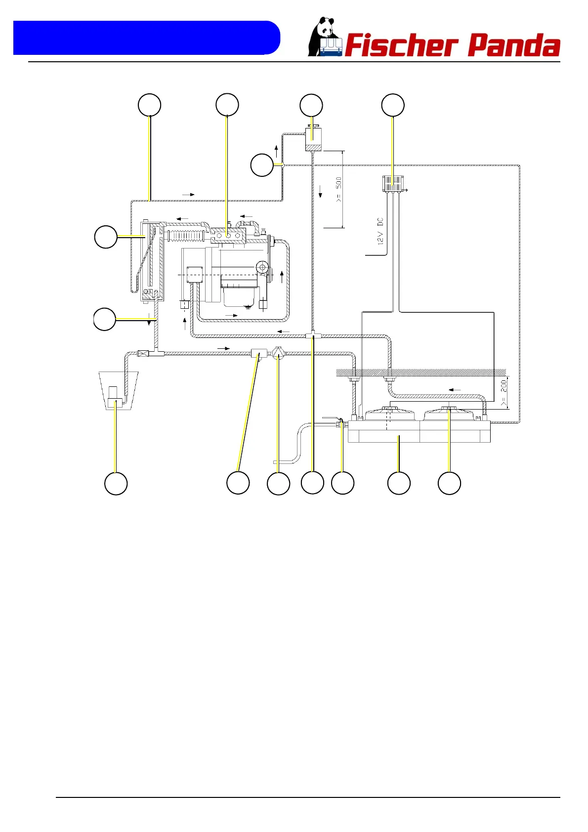
Fig. 6.8.17-2: Installation diagram for underneath the vehicle
03
04
06
05
01
08
09
11
12
02
10
13
07
05
01. Ventilation pipe
02. Water-cooled exhaust elbow
03. Coolant expansion tank
04. External fan control
05. Dry silencer
06. Exhaust outlet
07. T-piece with connection for Thermoswitch
08. External cooling water pump
09. Stop valve for coolant
10. T-piece
11. Radiator
12. Fan for radiator
13. Bucket with submerged pump
 Loading...