I&J7000 Series Operating Manual
Section 7: Specifications
Part # 561978B
Rev. H May 04
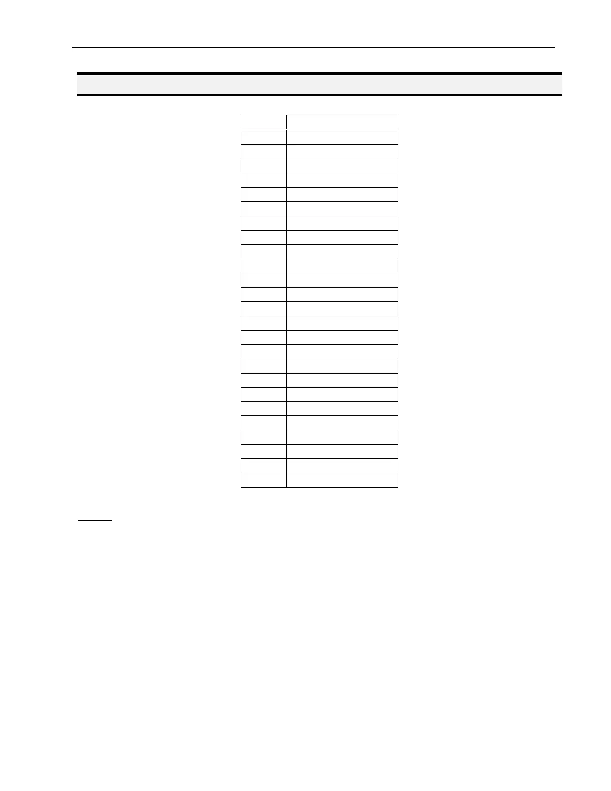
2.3. Input Signals
Notes:
1. To close an input signal, short the circuit between the input pin (26 – 33) and the GND
(pin 50).
2. Input signals are powered by the robot internal power supply: 5 volts, maximum 1.2 mA
3. Check the status of an input signal using the SET I/O command (see Section 6: 1.16
- Set I/O). When the input pin (pin 26 – 33) is connected to ground (pin 50), the value
of the input is 0.
 Loading...