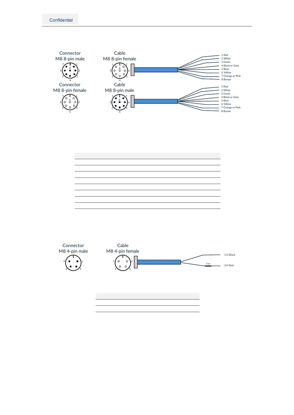
3.2.4. AUX connector
1
2
3
4
5
6
7
8
Connector
M88-pinfemale
7
6
5
4
3
2
1
8
Cable
M88-pinmale
1Red
2White
3Green
4BlackorGrey
5Blu e
6Yellow
7OrangeorPink
8Brown
1
2
3
4
5
6
7
8
Connector
M88-pinmale
7
6
5
4
3
2
1
8
Cable
M88-pinfemale
1Red
2White
3Green
4BlackorGrey
5Blu e
6Yellow
7OrangeorPink
8Brown
Figure 3.4.: AUX connector pin overview
Note: The Vision-RTK 2 exists in two variants. Variants manufactured before October 2022 were
equipped with male connectors on the sensor, and future sensors will contain female connectors.
Pin Wire color Symbol Description
1 Red +5V Voltage supply output of 5V
2 White UART2_RX UART receiver input 2
3 Green UART2_TX UART transmitter output 2
4 Black or Grey GND Signal ground
5 Blue Reserved Reserved
6 Yellow Reserved Reserved
7 Orange or Pink Reserved Reserved
8 Brown Reserved Reserved
Table 3.2.: Aux connector pin definition
3.2.5. Power connector
1
23
4
Connector
M84-pinmale
Cable
M84-pinfemale
1/2Black
3/4Red
4
32
1
Fuse
Figure 3.5.: Power connector pin overview
Pin Wire color Symbol Description
1/2 Black GND Power ground
3/4 Red VCC Main power input
Table 3.3.: Power connector pin definition
3.2.6. GNSS connector
The Vision-RTK 2 contains two GNSS receivers that can connect to an antenna via the
female SMA connectors labeled GNSS 1 and GNSS 2.
3.2.7. Wi-Fi connector
The Vision-RTK 2 can significantly increase its Wi-Fi range by connecting a Wi-Fi antenna
to the female RP-SMA connector labeled Wi-Fi.
Vision-RTK 2 | Fixposition Positioning Sensor 7