5.3. Input/output system overview
VRTK2 sensor
UART1 UART2 CANSTRTCPx
UART1
(RX/TX)
UART2
(RX/TX)
Network
(ethernet, Wi-Fi)
CAN
(CANL/CANH)
I/O connector
pins 7 and 8
AUX connector
pins 2 and 3
I/O connector
pins 1 and 2
ETH
connector
Wi-Fi
antenna
Host system
(example)
Port
Interface
Connector
Output messages
Fusion
GNSS
Input messages
Parser Parser Parser Parser
Wheelspeed
(RAWDMI)
Wheelspeed
CAN sensor
Wheelspeed
(CAN sensor)
RTK corrections
(RTCM3)
NTRIP
client
RTK corrections
(RTCM3)
Output messages
Input messages
Input/output stream
(of bytes)
Parser
to/from hostto/from host
Interface
Connector
to/from sensor
Interface
Connector
ROS
driver
to/from sensor
Application (e.g.,
a map display)
Wheelspeed
FP_A-ODOMETRY,
NMEA-GP-GGA, ...
ROS nav_msgs/
Odometry, ...
ROS msg/SpeedNOV_B-RAWDMI
GNSS corr.
RTCM3 messages
NTRIP
caster
to/from host
to/from host VRTK2 NTRIP client actively
requests corrections
VRTK2 actively queries CAN bus
for wheelspeed
Host sends wheelspeed
resp. corrections to sensor
Host sends
wheelspeed to sensor
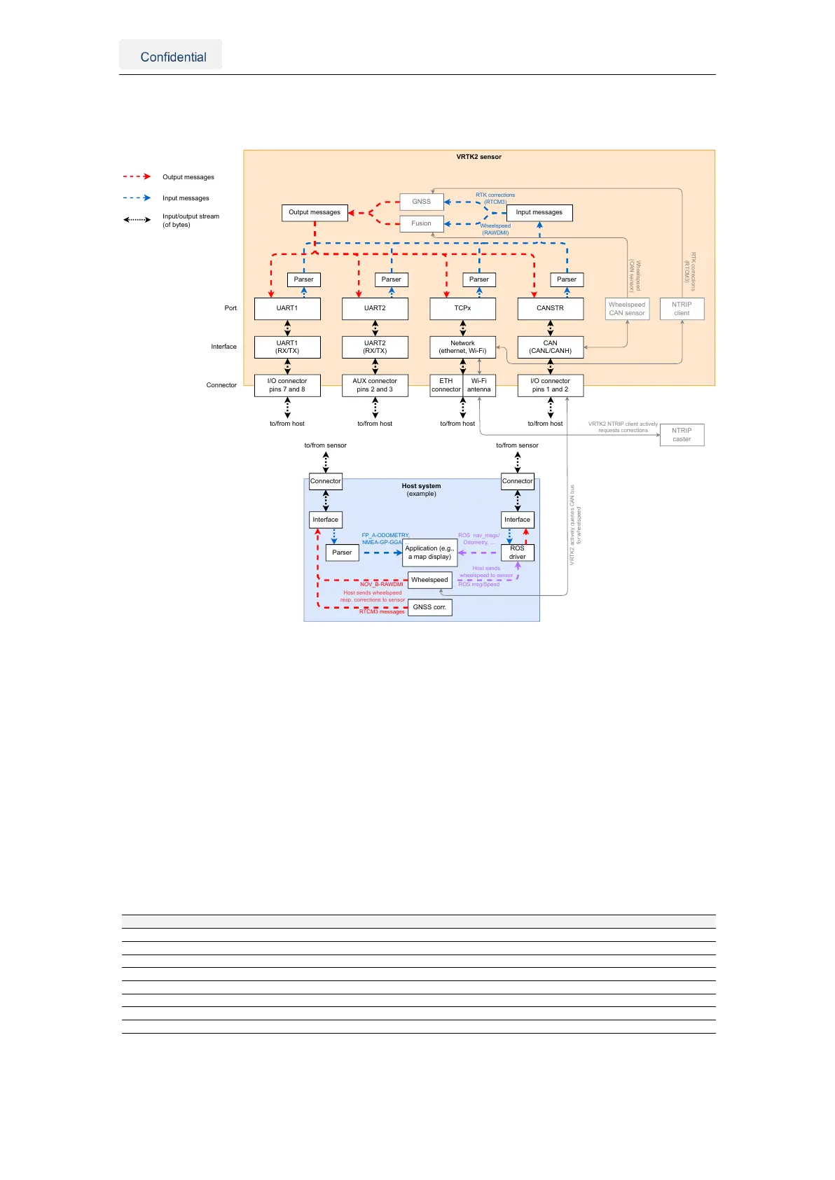
Figure 5.6.: Input/output system overview
The Vision-RTK 2 provides multiple input and output data stream options. This section
provides an overview of the I/O system. Note the distinction between:
• Port: Physical (e.g., UART) or logical (e.g., network socket) connection endpoint.
Via a connector and an interface this is what the customer ultimately connects to.
• Interface: Hardware peripheral which connects a port with a connector.
• Connector: Provides the electrical connection to the interface (i.e., the connector
names are written on the sensor).
The network interfaces of the sensor comprise Ethernet, Wi-Fi station (client), Wi-Fi ac-
cess point, and USB network. See Section 5.2 for more details on network configuration.
Port Interface Connector Description
UART1 UART1 I/O (Asynchronous) serial port for speed up to 1Mbit/s, via a UART1 interface
UART2 UART2 AUX (Asynchronous) serial port for speed up to 1Mbit/s, via a UART2 interface
TCP0 Network Eth, Wi-Fi, USB TCP/IP raw socket server on port number 21000, can handle multiple clients
TCP1 Network Eth, Wi-Fi, USB TCP/IP raw socket server on port number 21001, can handle multiple clients
TCP2 Network Eth, Wi-Fi, USB TCP/IP raw socket server on port number 21002, can handle multiple clients
TCP3 Network Eth, Wi-Fi, USB TCP/IP raw socket server on port number 21003, can handle multiple clients
TCP4 Network Eth, Wi-Fi, USB TCP/IP raw socket server on port number 21004, can handle multiple clients
CANSTR CAN I/O CAN “streaming” port. Broadcasts output messages and listens to incoming messages
Table 5.3.: Connector, Interface, Port overview
Vision-RTK 2 | Fixposition Positioning Sensor 19