5.3.1. UART port configuration
The UART1 and UART2 ports correspond to the pins 7 (UART1_RX), 8 (UART1_TX), 4
(GND) in the I/O connector, and pins 2 (UART2_RX), 3 (UART_TX), and 4 (GND) in the
AUX connector (see Subsection 3.2 for more information). The user can configure the
baud rate of the UART ports inside the "Configuration → I/O" panel of the ieb interface.
The available options are 9’600, 19’200, 38’400, 57’600, 115’200, 230’400, 460’800, or
921’600. A baud rate of 115’200 or higher is recommended.
The user can input the wheelspeed sensor and RTCM3 correction data streams into the
Vision-RTK 2 via UART (see Section 5.7 and Section 5.4, respectively). The Vision-RTK
can stream the output messages (e.g., FP odometry) via UART (see Subsection 5.3.4).
I/O ports
UART1
Baudrate
UART2
Baudrate
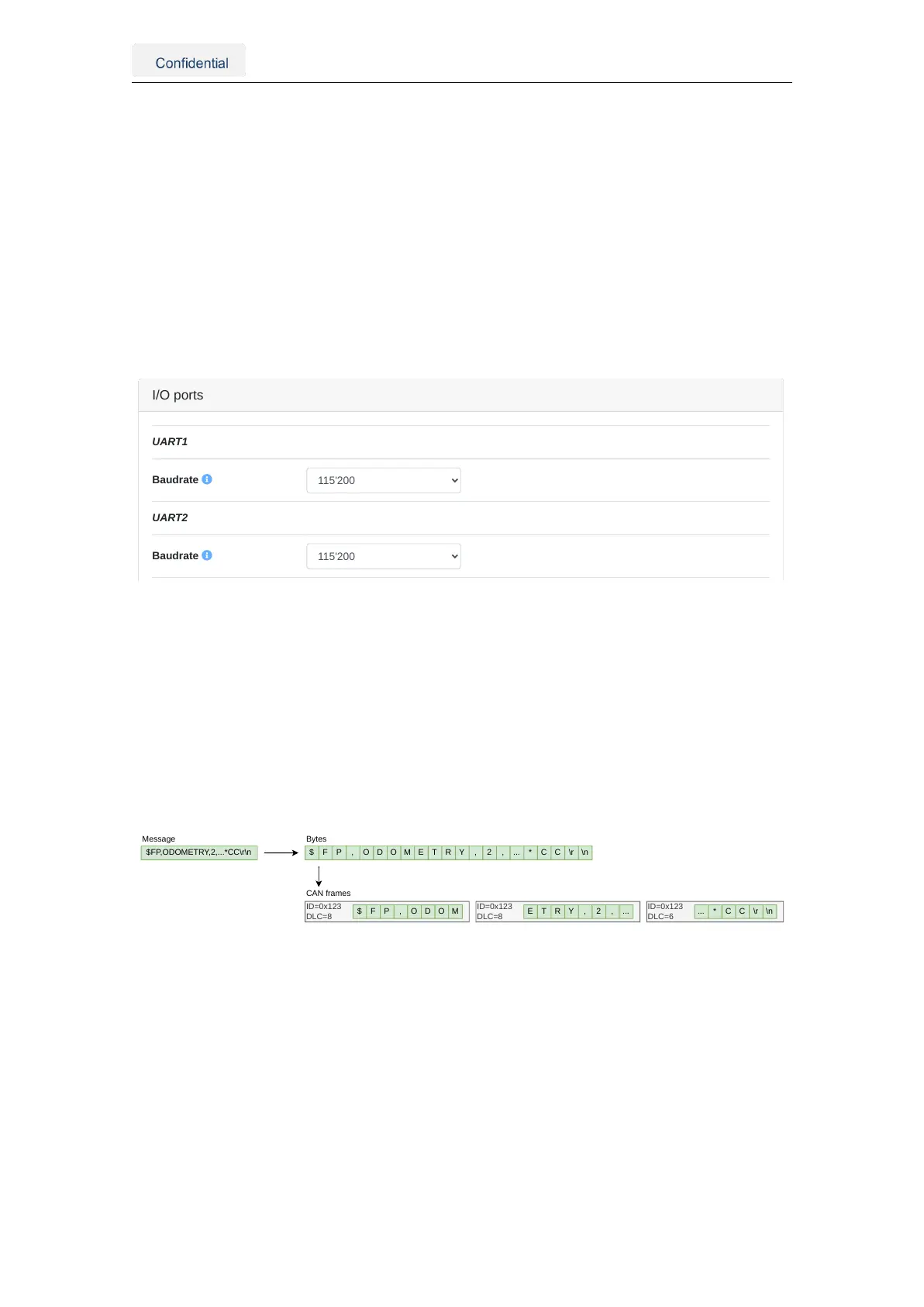
Figure 5.7.: UART baud rate configuration
5.3.2. CAN streaming port configuration
All input and output ports are streams of bytes (uint8_t). The CANSTR port packs the out-
put stream of bytes into as many CAN frames as necessary. Depending on the CANSTR
configuration, this can be classical CAN frames with up to 8 bytes or CAN FD frames with
up to 64 bytes of payload. Figure 5.8 shows the CANSTR message format generation.
The CANSTR port corresponds to the pins 1 (CANH), 2 (CANL), and 4 (GND) of the I/O
connector (see Table 3.1).
$FP,ODOMETRY,2,...*CC\r\n
ID=0x123
DLC=8
$ F P , O D O M E T R Y , 2 , ... * C C \r \n
ID=0x123
DLC=8
ID=0x123
DLC=6
$ F P , O D O M E T R Y , 2 , ... ... * C C \r \n
Message Bytes
CAN frames
Figure 5.8.: CANSTR message format
The user can configure the CAN interface inside the "Configuration → I/O" panel of the
web interface, as shown in Figure 5.9. The following configuration options are available:
• CAN interface: The CAN interface can be enabled or disabled.
• Classical CAN bitrate: The bitrates [Hz] can be: 10’000, 20’000, 50’000, 125’000,
250’000, 500’000, 800’000 or 1’000’000.
• CAN FD (BRS) bitrate: The CAN FD bitrate must be greater or equal to the classi-
cal CAN bitrate.
The user must reboot the sensor after updating the CAN interface configuration.
Vision-RTK 2 | Fixposition Positioning Sensor 20