(a) Ground robot: The horizon line lies in the middle
of the camera frame.
(b) Car: The hood covers almost half of the frame,
preventing feature acquisition.
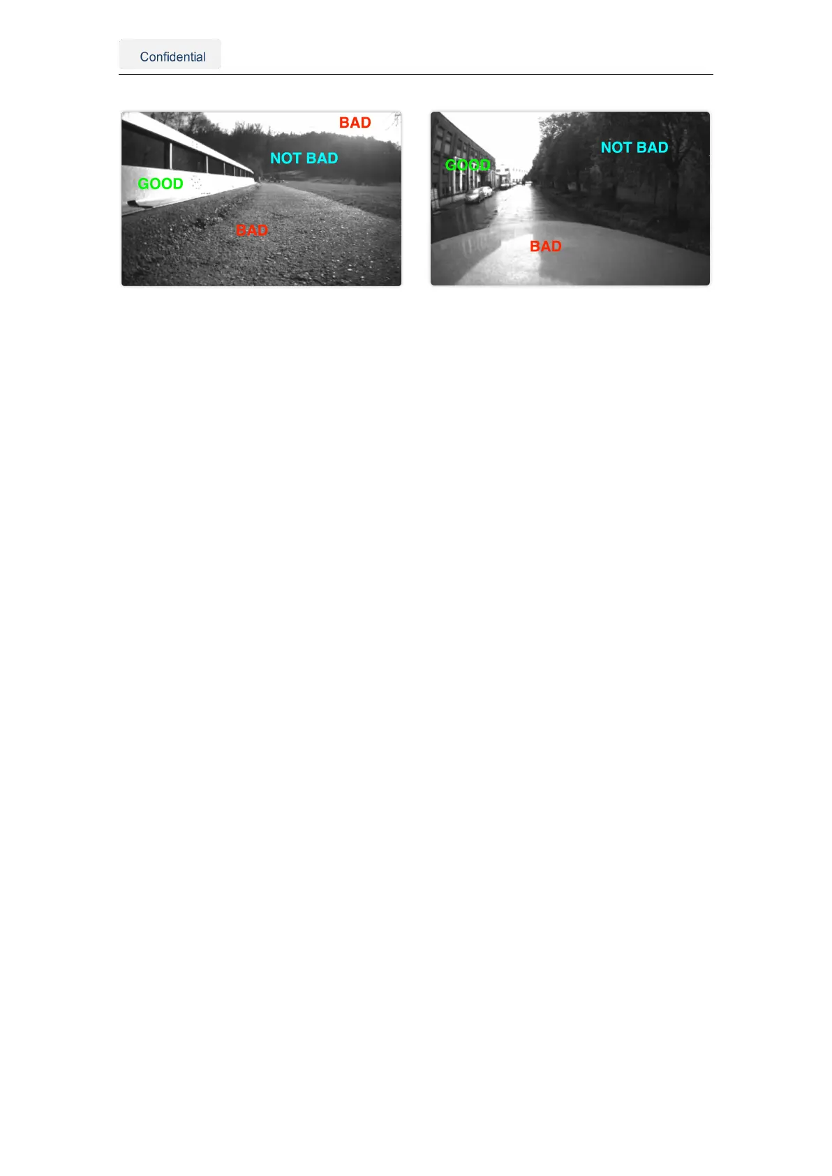
Figure 4.2.: Obstructions and featureless scenes in the camera view
4.2. Other considerations
• Use a power source between 10-24 V (min 4.5V and max 40V).
• Employ high-quality coaxial cables with minimal signal attenuation and delay with a
male SMA connector.
• Select antennas and a correction service that supports L1 and L2 bands for as
many satellite constellations as possible (See Appendix E).
• wheelspeed can improve performance in GNSS outages; however, excessive slip-
page may be detrimental. Assess whether incorporating this data benefits you.
• Consider the camera FOV data when integrating the sensor (See Appendix D).
• The Vision-RTK 2’s performance is not affected by whether the sensor is facing
backward or forward in the direction of movement.
• Under ideal conditions, the high-precision GNSS receivers employed by the Vision-
RTK2 can deliver accuracy down to the centimeter level: 0.01 m + 1 ppm circular
error probable (CEP) - measured using a 1 km baseline and patch antennas with
good ground planes. Thus, if the sensor connects to a base station located 20 km
away, the receiver can provide an accuracy of approximately 3 cm. It is worth noting
that the degradation rate increases significantly for distances longer than 20 km.
4.3. Maintenance procedure
To ensure the long-lasting adequate performance of the sensor, the user must periodically
perform the following steps:
• Clean the camera lens from any obstructions.
• Verify the integrity of all cables.
• Tighten all connections to the sensor.
• Ensure the sensor and the GNSS antennas are firmly attached to the structure and
rigid with respect to each other.
Vision-RTK 2 | Fixposition Positioning Sensor 11